Understanding Q-DEMO: the work connecting Japan’s demonstration reactor to a power-generating system
An in-depth feature explaining Q-DEMO’s staged power-generation demonstrations through the connections between heat, fuel, materials, maintenance, and safety—from technology inherited from JT-60SA and ITER to costs, implementing organizations, and deliverables companies can provide.
Read the Japanese original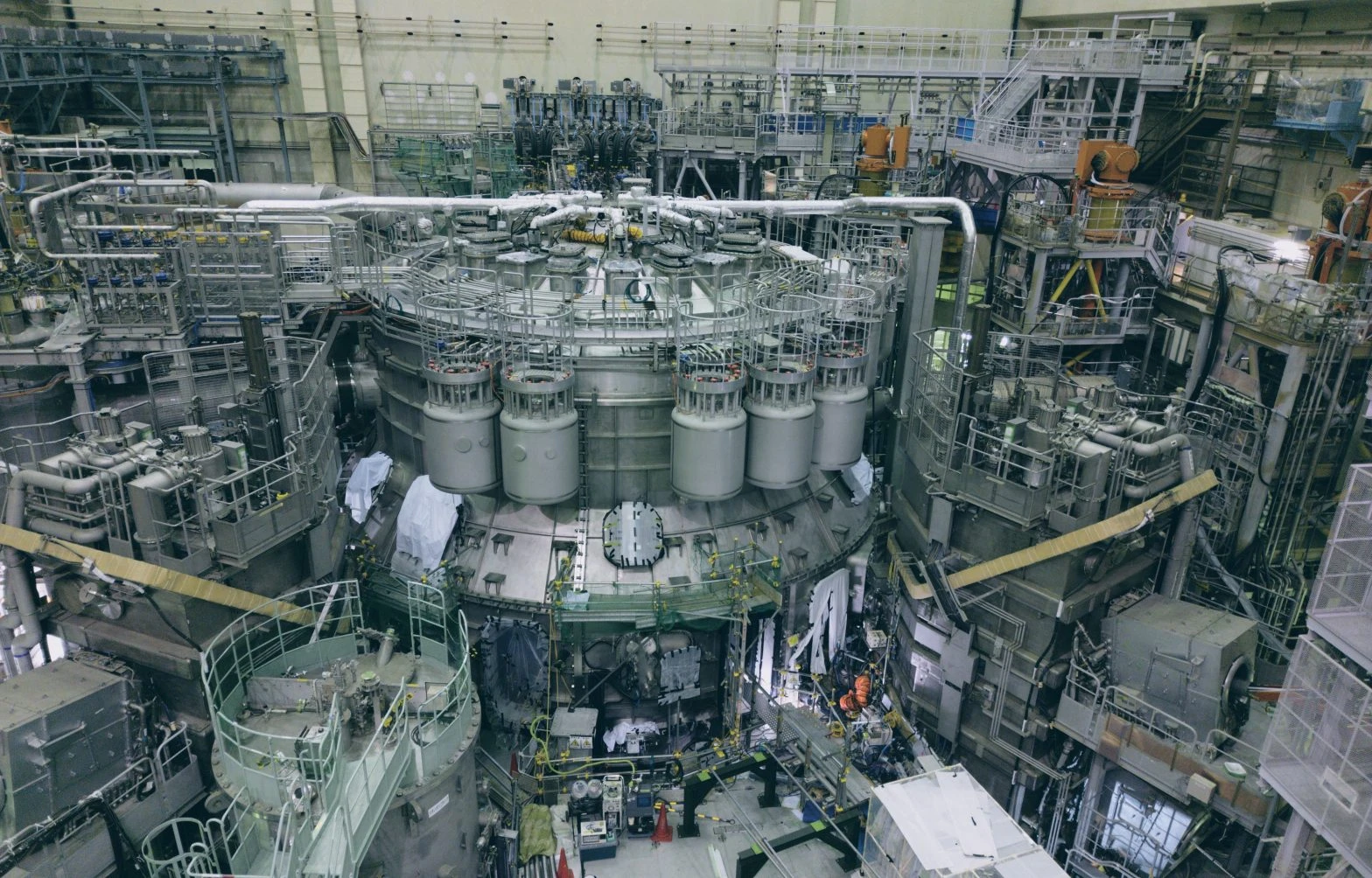
Understanding Q-DEMO requires looking beyond the doughnut-shaped reactor to the generators, fuel facilities, and replacement work outside it. Many technological connections lie between extracting energy from high-temperature plasma and producing electricity that can be used continuously.
Japan's Q-DEMO demonstration-reactor concept is a plan to verify those connections in stages. Alongside technology development, specifying costs and the implementing organization remains an issue; announcing a power-generation target is not equivalent to deciding to build. This is not a new construction announcement, but an in-depth explanation of the work needed to demonstrate electricity generation, based on public materials available on October 14, 2026. For an overview first, see our Q-DEMO introduction.
Summary
- Q-DEMO is QST's ITER-sized demonstration-reactor concept, not simply a new name for the former JA DEMO.
- The concept demonstrates electricity generation, fuel breeding, and steady-state operation in stages. First electricity does not mean all problems have been solved.
- Industry connections extend beyond the reactor to heat transport, fuel recovery, materials evaluation, remote maintenance, and diagnostics and control. Technical need and actual procurement are nevertheless different things.
Contents
- What changed from JA DEMO?
- What do the three stages demonstrate?
- What is inherited from JT-60SA and ITER?
- From plasma performance to power-plant performance
- Extracting heat and fuel in the blanket
- Producing fuel alone does not establish self-sufficiency
- Transporting heat and converting it into electricity
- Examine test conditions when selecting materials
- Materials-testing facilities are also built in stages
- Replaceable designs support availability
- Building safety through equipment and operations
- Where can companies consider participating?
- How to assess the next advances
What changed from JA DEMO?
QST explains that JA DEMO, whose basic concept was clarified in 2019, envisaged demonstrating electricity generation around the middle of this century. Q-DEMO integrates JA DEMO studies and ITER's engineering design as an accelerated approach targeting a power-generation demonstration in the 2030s. Choosing a scale comparable to ITER is intended to use accumulated experience in equipment manufacture and construction. QST's positioning of Q-DEMO
Interpreting this as “smaller means easier” misses the point. Magnets, the vacuum vessel, heat-receiving components, and maintenance access must fit within limited space while meeting their respective requirements. Selecting technologies available early and leaving room for later performance improvements are simultaneous challenges.
Conceptual design here means examining the feasibility of major configurations and performance—not that construction or operation has occurred. Dimensions, output, and component shapes from earlier JA DEMO materials cannot simply be copied as finalized Q-DEMO specifications. The starting point is to distinguish the common purpose of a demonstration reactor from the differences between individual design concepts.
What do the three stages demonstrate?
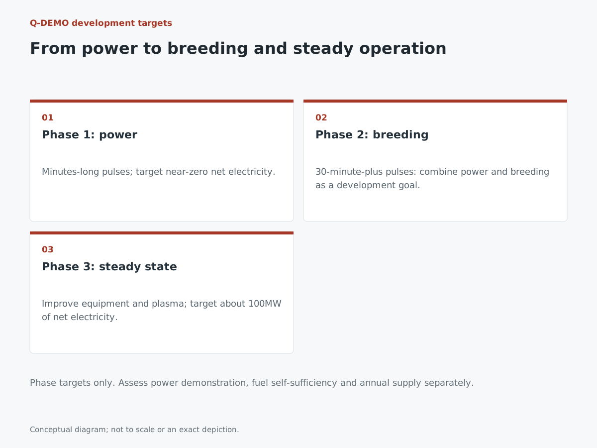
QST's conceptual-design overview describes Stage 1 as power generation on a net-zero-electric-power scale using short pulses of several minutes; Stage 2 as electricity generation and fuel breeding using long pulses of at least 30 minutes; and Stage 3 as steady-state operation with approximately 100 MW of net electric power. All are development goals, not current achievements. Q-DEMO conceptual-design overview
“Net” means subtracting the electricity consumed within the plant from the electricity generated. Evaluation covers not only whether the generator turned, but also what was used to heat the plasma and run pumps and cooling equipment. Power during operation and total energy over a sequence including startup and shutdown are also different metrics. When reading demonstration-reactor results, check the boundary included in the reported balance.
Separating stages makes clear what will be verified first and what remains for later improvements. Conversely, interpreting initial power generation as “fuel self-sufficiency and electricity available at any time” erases the later challenges. Performance headlines must always identify the stage demonstrated.
What is inherited from JT-60SA and ITER?
JT-60SA is a joint Japanese-European project for plasma research supporting ITER, complementary research toward a demonstration reactor, and training people. It studies operating methods such as maintaining high-pressure plasma for long periods. It is not a power plant testing every demonstration-reactor function at smaller scale. QST's JT-60SA project introduction, updated April 21, 2026
ITER is an experimental device for testing long-pulse operation and related technologies at reactor scale; it is not a project equipped to generate electricity. This distinction is also important to understanding what ITER is. Q-DEMO must consider equipment converting heat into electric power as well. ITER's official explanation
Transferring knowledge means more than copying drawings. It includes experience with the order in which large components were installed, what inspections revealed, and how behavior during operation was measured. However, components that worked in an existing machine may not work at new temperatures, neutron environments, or operating durations. Work is needed to identify which conditions can be carried over and which require new tests.
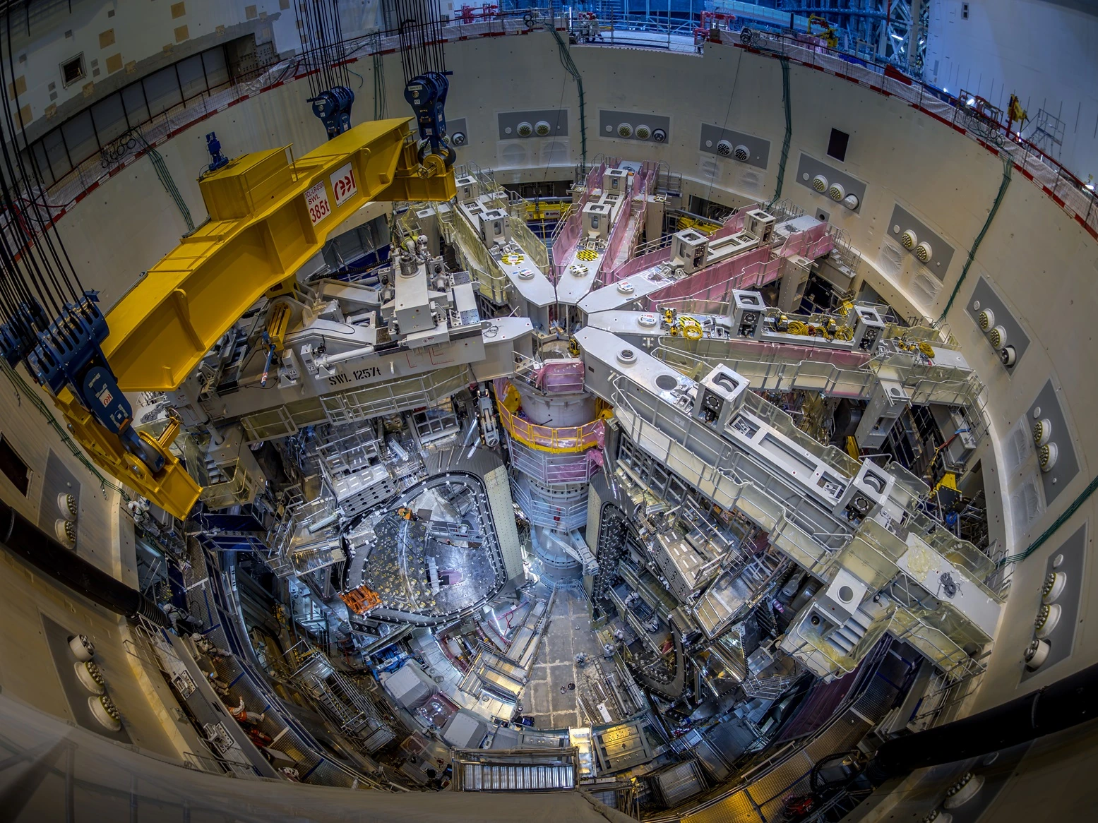
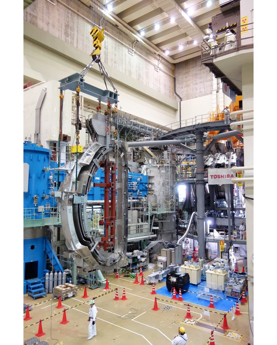
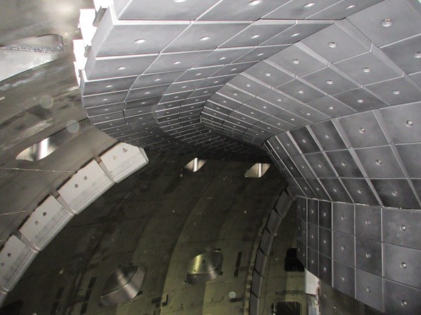
The photographs show these existing related facilities. They do not depict a completed Q-DEMO reactor or its construction site.
From plasma performance to power-plant performance
A tokamak confines high-temperature plasma with strong magnetic fields. Core design must consider force balance, stability, and heat transport consistently. Selecting one maximum temperature or density does not automatically produce the desired fusion power. Core-plasma explanation by the Joint Special Design Team for Fusion DEMO
Fusion energy gain Q expresses the relationship between external heating supplied to the plasma and fusion power, not the electrical balance of the entire power plant. Comparisons become clearer when readers keep three boundaries in mind: “the plasma,” “the heat-extraction system,” and “the entire power plant.” The difference between energy gain and electricity generation (Japanese)
Imagine a design meeting to see why these connections are difficult. A change improving plasma performance may alter heat arriving at the wall or fuel-supply conditions. Changing the wall geometry or cooling method in response can then affect maintenance space or manufacturing methods. It is not enough for each team to maximize its own performance: it must choose performance compatible with neighboring equipment. Demonstration-reactor development also means supporting this coordination through tests and calculations.
Extracting heat and fuel in the blanket
The blanket is in-vessel equipment placed around the plasma. It receives energy from fusion neutrons as heat and, in a fuel-breeding configuration, produces tritium from lithium-containing materials. Heat recovery and fuel production intersect in the same location. Blanket principles
This component is not completed simply by building a sturdy metal box. Internal flow channels, material arrangements, joints, and inspectable locations must be considered so heat can be transported while mechanical integrity is maintained. Measuring material properties in a laboratory, manufacturing near-full-scale components, and verifying function inside a reactor provide different types of evidence.
The divertor, meanwhile, is involved in exhausting helium and other particles and removing heat. Although both are “equipment inside the reactor,” their required roles differ. The divertor's role
Companies proposing components should pair intended use with test conditions rather than showing strength or thermal conductivity alone. What will be cooled, what will be joined, and what degradation will be detected? Sharing these questions with designers is a first step toward aligning general materials and processing technologies with demonstration-reactor requirements. This is business analysis, not evidence of adoption or procurement of a particular material.
Producing fuel alone does not establish self-sufficiency
The fuel system includes not only deuterium and tritium supply but also exhaust of unburned fuel, impurity removal, isotope separation, storage, and recovery from the blanket. Fuel unused in the reaction needs a route back to a reusable state. The overall fuel system
“Breeding was achieved” and “fuel self-sufficiency is possible” are not the same conclusion. One must also consider whether the produced fuel can be recovered, returned to the supply side in time, and accounted for wherever it remains in the equipment. Time and inventory management, not just quantity, become operating conditions for the power plant.
For example, even a high-performing recovery unit cannot prevent the overall flow from stalling if another process stops. Conversely, a configuration allowing part of the system to be isolated for inspection changes the operational options. Design should be linked to operating procedures down to which equipment states trigger a supply shutdown and how decisions are made when measurements are uncertain.
Companies may also find connections in analysis and measurement, vacuum systems, separation, leak management, and operating records. However, looking similar to existing industrial equipment does not mean the same operating conditions apply. Applicability must be assessed after checking the substances involved, required confinement, and constraints on inspection and maintenance.
Transporting heat and converting it into electricity
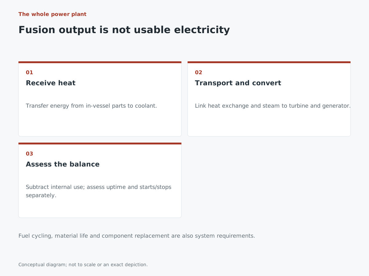
In a demonstration-reactor plant, heat transferred from in-vessel components to coolant is carried to heat exchangers and other equipment, with steam driving a turbine and generator. Simply adding a generator does not complete the plant: systems for receiving, transporting, and converting heat must be connected. Main heat-transport system and electricity generation
The boundaries between components matter. The temperature and time variation of heat delivered by the reactor must match what the receiving system can tolerate. Short pulses and steady-state operation do not necessarily use equipment in the same way. It is necessary to consider which equipment continues working, including during shutdown.
Expectations that “existing power-generation technology can be used” therefore need separate assessment at the component and integrated-system levels. Turbine and heat-exchange experience is important, but connection and validation for demonstration-reactor conditions remain. Company proposals become more concrete when they explain response to fluctuations, inspection conditions, and ease of replacement, not just standalone efficiency.
When reading future demonstrations, look beyond the instantaneous electricity output to duration, internal consumption, and balances including startup and shutdown. This allows proper recognition that “electricity was generated” while retaining the separate question of whether the system has moved closer to supplying power throughout the year.
Examine test conditions when selecting materials
Reactor materials operate under neutron exposure. Evaluation depends on test temperature, irradiation conditions, specimen shape, and manufacturing history. Even with the same material name, different joints or post-processing states change what must be checked. A considerable gap separates finding an excellent material-property value from assembling a design basis for using it in equipment.
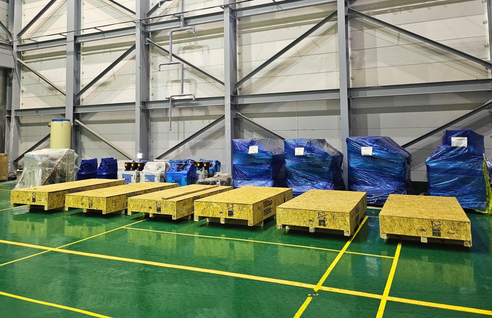
As an example of taking materials into real components, F4E reported delivery of EUROFER97 steel for ITER test-blanket development on July 8, 2024. The photograph shows a moment in that material supply, not adoption or delivery of Q-DEMO materials. F4E material-supply report
QST's materials-research explanation introduces ion irradiation as a way of simulating neutron damage while noting its limitation: effects are confined near the surface. Each test method has a range where it is useful; one result cannot be extended to every condition in a real machine. QST's explanation of materials testing
Materials-testing facilities are also built in stages
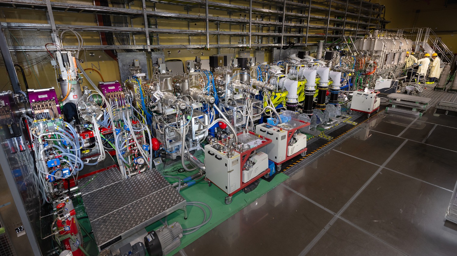
LIPAc, being developed in Rokkasho, validates accelerator technology for a future materials-irradiation facility. On April 29, 2026, F4E reported that assembly of the full configuration, including the superconducting radio-frequency accelerator section, was complete and that it would move to the next testing phase. F4E LIPAc report
The accelerator overview photograph shows that equipment supporting materials research also goes through assembly and integration with cooling and controls. Having the full configuration assembled, achieving the target continuous-beam operation, and verifying material lifetimes in a power reactor are separate achievements.
When following test-facility progress, check what “completion” refers to. Does it mean the building, machine assembly, operating performance, or the test environment users need? Recognizing those differences reveals development sequences that are easy to miss when looking only at the demonstration reactor itself.
Replaceable designs support availability
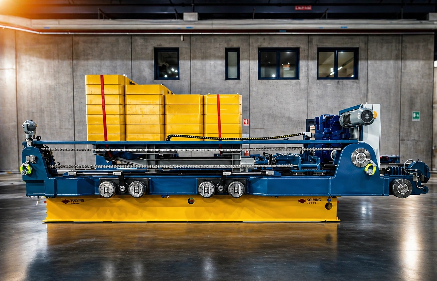
In-vessel blankets and divertors are designed to be replaced. Remote maintenance includes not only removal machinery but systems for transporting components under confinement and handing them over to maintenance areas. Remote maintenance and the role of casks
Replacement is not a final add-on of “fix it with a robot if it breaks.” Conditions such as tool access, pipe disconnection, and heavy-load transport must be built into components from the outset. Longer maintenance shutdowns mean more time without electricity generation. From a business perspective, design for continued use deserves as much attention as peak output.
In a concrete Japanese initiative, QST, Sojitz Machinery, and Sugino Machine announced on February 9, 2026 that they had begun manufacturing ITER initial-assembly tools using technology developed for remote maintenance. This illustrates R&D technology being applied to another task. However, starting ITER tool manufacture does not demonstrate completion of Q-DEMO's entire maintenance system. Joint announcement by the three parties
Building safety through equipment and operations
Fusion safety cannot be fully explained merely by comparing whether its mechanism is the same as a fission reactor's. Device-specific conditions must be addressed, including tritium-fuel management, neutron activation of materials, and energy stored in equipment. Discussing safety measures is distinct from completing authorization or review for a particular facility.
Safety is easier to explain by separating “inherent characteristics,” “design provisions,” “performance verified by tests,” and “procedures followed during operation.” For example, explaining confinement requires addressing not only normal conditions but connections to abnormality detection, shutdown, and inspection. Safety is not a function assigned to one component, but a combined issue of design, measurement, operation, and maintenance.
The government's March 25, 2025 “Basic Approach to Ensuring Safety” distinguishes treatment of cases with risks comparable to existing devices from studies needed for future demonstration reactors and similar facilities. Publishing this basic approach should not be treated as enactment of a new law or individual authorization for Q-DEMO. Basic Approach to Ensuring Safety
Where can companies consider participating?
Companies considering entry have options other than winning an entire demonstration-reactor contract from the outset. Public requirements can be broken into deliverables the company can validate. Examples include joining or machining combined with inspection in manufacturing; measurement range and uncertainty in diagnostics; work procedures and required time in maintenance; and linking design changes to equipment histories in information systems.
A concrete example is QST's procurement notice posted on October 9, 2026 for investigation and study of demonstration-reactor reliability and maintainability evaluation and engineering-data management. It shows work to incorporate failures, maintenance, and information management into design, not just component performance. Posting a notice must not be reinterpreted as contract signing, work completion, or achievement of high demonstration-reactor availability. QST procurement notice
Another concrete example illustrates the scope of evaluation. The September 2026 specification for “Engineering Design Study of Protective Limiters in Q-DEMO” considers responses to heat, stress, and electromagnetic forces with reference to ITER divertor technology, but explicitly excludes fatigue evaluation from this work. QST's public specification
Fatigue is damage progressing under repeated loads. Even completing this work would not establish that lifetime under repeated operation had been evaluated. Rather than treating a limited scope as a defect in itself, the important approach is to connect the present deliverables to what needs checking next. The specification also describes ongoing engineering-design activities, showing work becoming more concrete in individual design studies after publication of the concept.
The following are four questions the editorial team proposes for considering entry.
- Which problem in which component does the company's technology solve?
- Where is the boundary between proven conditions and those requiring additional tests?
- Is the deliverable a physical item, analysis results, test data, or operating procedures?
- Can inspection results and manufacturing/change histories be explained so the customer can decide whether to adopt it?
Research prototypes, full-scale tests, and manufacturing for actual machines require different capital investment and scopes of responsibility. Early business plans become more concrete by considering what can be supplied for the next test or design decision rather than projecting revenue first from large future-market forecasts. Public technical challenges are material for exploring opportunities, not guarantees of orders for individual companies.
How to assess the next advances
For Q-DEMO, technological goals and business decisions must be considered side by side. Materials for the Cabinet Office's first Fusion Process Review Committee on August 10, 2026 identified construction costs and the implementing organization as issues. They proposed near-term work to refine and rationalize costs through engineering design and specify the implementing entity. The document's “summary” is a draft; it cannot be taken as approval to build or a decision to cancel the plan. Cabinet Office discussion materials, August 10, 2026
Future news should therefore distinguish at least three kinds of progress. First, tests and analyses reduce technological uncertainty. Second, costs, responsibilities, and implementation arrangements become more concrete. Third, formal construction or operating decisions are made. Not extending one advance to imply achievement of the other two allows both expectations and challenges to remain in view.
Q-DEMO's significance is that it broadens the question from research that produces fusion to a system that extracts heat, circulates fuel, and generates electricity while components are replaced. Making a power plant real requires work outside the conspicuous reactor core just as much as inside it. Understanding those connections concretely provides a foundation for following Japan's fusion industry over time and considering how to participate.
- QST’s positioning of Q-DEMO (checked October 14, 2026)
- Q-DEMO conceptual-design overview (checked October 14, 2026)
- QST’s JT-60SA project introduction, updated April 21, 2026 (checked October 14, 2026)
- ITER’s official explanation (checked October 14, 2026)
- Core-plasma explanation by the Joint Special Design Team for Fusion DEMO (checked October 14, 2026)
- Blanket principles (checked October 14, 2026)
- The divertor’s role (checked October 14, 2026)
- The overall fuel system (checked October 14, 2026)
- Main heat-transport system and electricity generation (checked October 14, 2026)
- F4E material-supply report (checked October 14, 2026)
- QST’s explanation of materials testing (checked October 14, 2026)
- F4E LIPAc report (checked October 14, 2026)
- Remote maintenance and the role of casks (checked October 14, 2026)
- Joint announcement by the three parties (checked October 14, 2026)
- Basic Approach to Ensuring Safety (checked October 14, 2026)
- QST procurement notice (checked October 14, 2026)
- QST’s public specification (checked October 14, 2026)
- Cabinet Office discussion materials, August 10, 2026 (checked October 14, 2026)
Information checked as of:2026-10-14
In-depth explanation based on public primary sources. Q-DEMO performance and electricity generation in the 2030s are targets, not achievements. The summary in the August 10 Cabinet Office materials is a draft. October 9 procurement is a notice, not evidence of contract signing or completion. Photographs record related existing equipment and materials, not an actual Q-DEMO machine. Unspecified original publication/update dates are distinguished from access dates; general market-entry discussions are editorial analysis.