Why JT-60SA heated its vacuum vessel to 200°C before making plasma
Gas released from the walls briefly raised the pressure. JT-60SA’s commissioning records show how engineers baked the vessel while cooling the superconducting magnets.
Read the Japanese original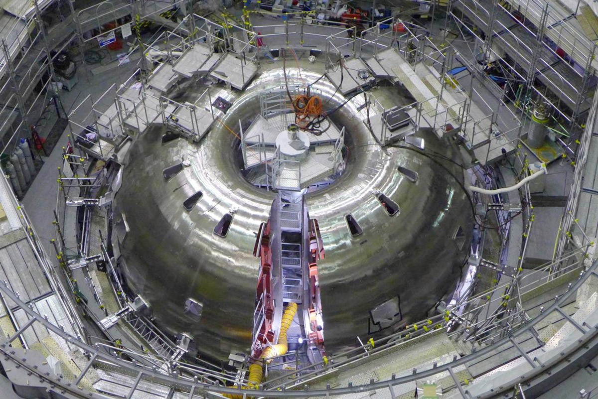
The vacuum pumps were running, yet the pressure inside the vessel rose. During commissioning in 2023, Japan’s JT-60SA fusion experiment in Naka, Ibaraki, heated its vacuum vessel from 50°C to 200°C before first plasma. Why do something that raises the pressure when the aim is to lower it? The answer lies in what stays on the walls after the air has been pumped out.
After the air is gone, water remains on the walls
The pumps first remove the air. Water can still cling to the walls and to components inside the vessel. QST’s 2020 commissioning record identifies moisture on the carbon tiles covering part of the central column and the upper divertor as one of the things the team had to remove.
Heating dislodges molecules from the surface. That extra gas can briefly raise the pressure even as the pumps keep working. As the pumps remove the gas and less of it comes off the walls, the pressure drops. QST’s July 2023 notes report just that: the pressure rose during baking and fell to a lower level afterward. The rise was part of clearing away what the walls had been holding.
Hot nitrogen flows between two steel shells
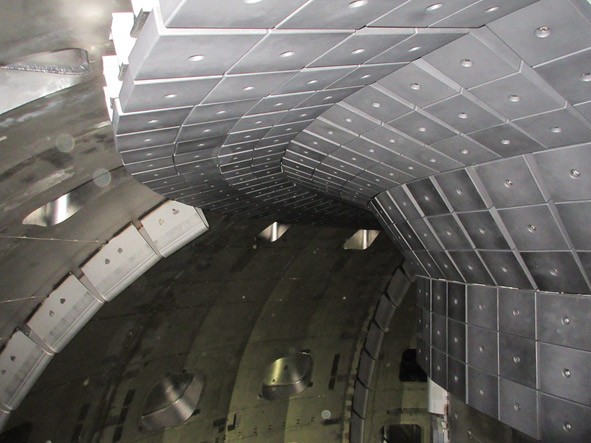
JT-60SA heats the torus by sending warmed nitrogen gas between two stainless-steel shells. The experimental space inside the inner shell is pumped separately. QST says that in normal operation the vessel is held at 50°C. The team raised it to 200°C to drive off moisture and other impurities.
The coils were getting colder at the same time. QST recorded the superconducting coils cooling from 80 K toward a target of 4.5 K in July 2023. Helium gas at about 80 K cools the thermal shields that limit heat transfer to the coils. The refrigeration plant uses liquid nitrogen to precool the helium. The hot nitrogen between the vessel walls flows through a separate circuit.
Leak tests check for gas getting in
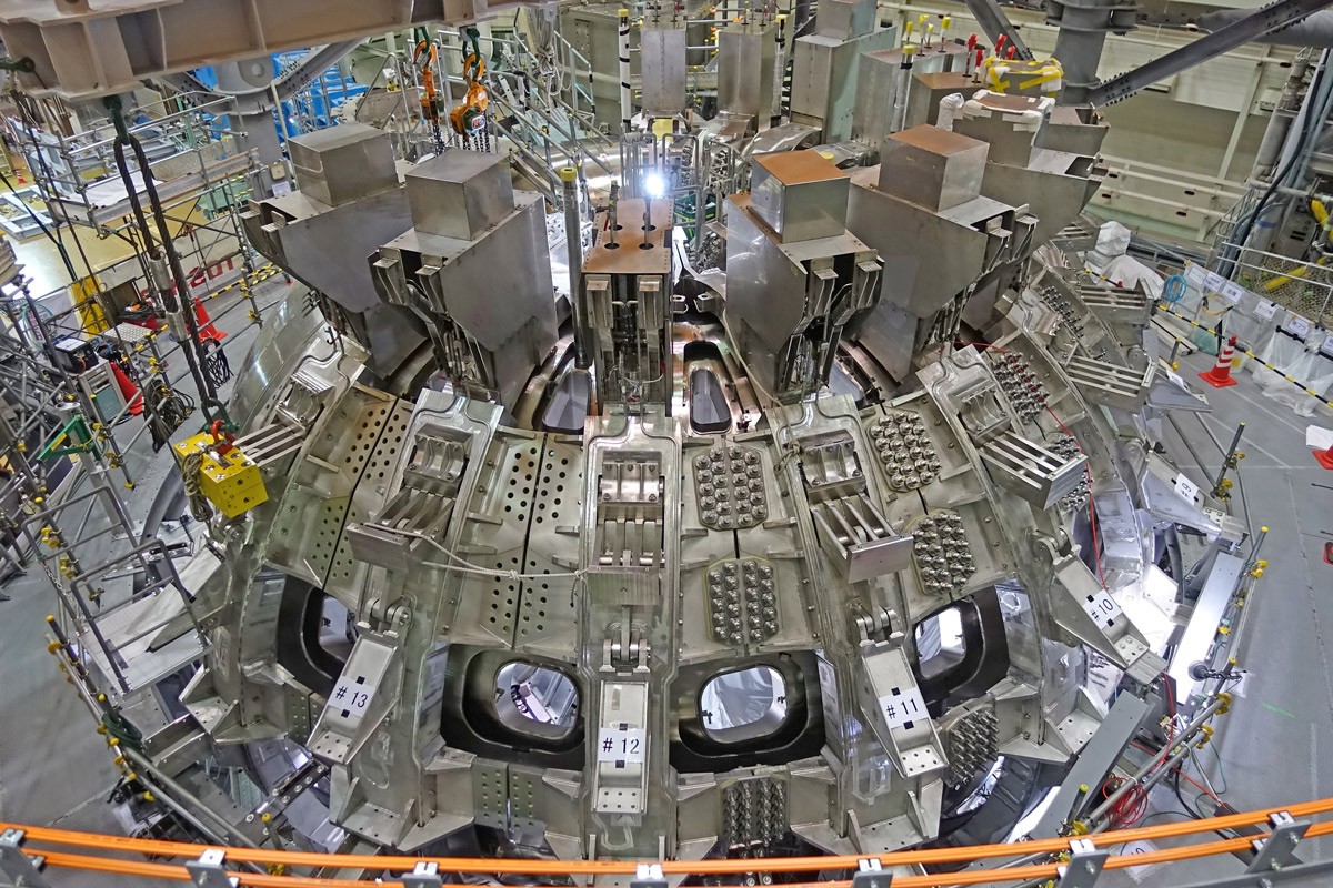
A pressure reading alone cannot tell you where the gas came from. Baking reduces what is left on the inner surfaces. A leak test looks for paths through which gas can enter. In November 2020, QST reported finding no leaks in tests at 260 locations on the plasma vacuum vessel and 270 on the cryostat that helps insulate the magnets.
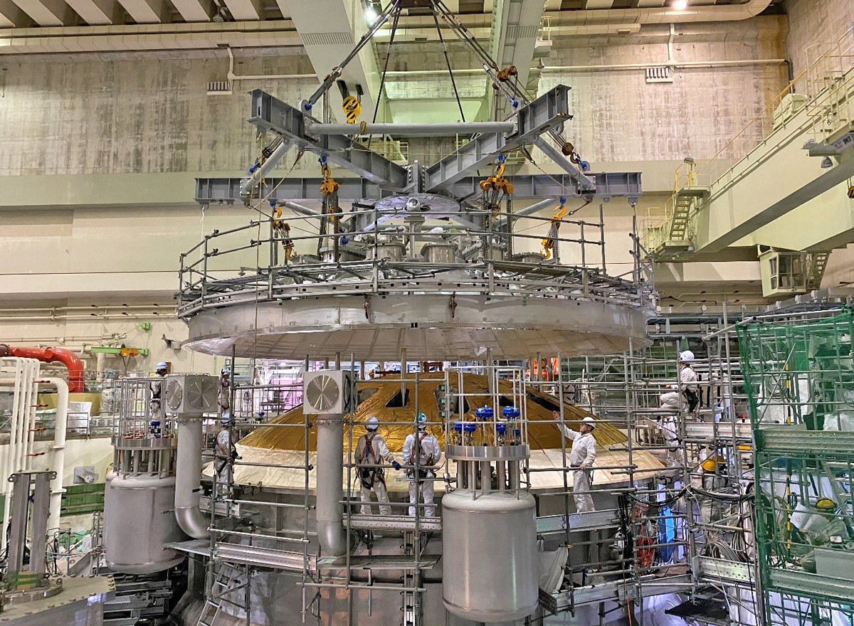
ITER also uses separate vacuum systems for the plasma vessel and for insulating the magnets. The assembly photographs show the vessel, the magnets around it, and the lid over both. Looking at those layers makes it easier to see where heat is added, where it is removed, and where gas is pumped out. All three jobs have to work together before first plasma.
Explore the JT-60SA device · How ITER’s cryopumps keep pumping
Official information from related companies and research institutions
Check each organization’s announcements for development progress and technical documentation.
- QST: JT-60SA vacuum vessel baking during commissioning (19 July 2023)
- QST: JT-60SA commissioning records (November and December 2020)
- ITER Organization: Vacuum system
- Fusion for Energy: JT-60SA assembly and photographs
- Fusion for Energy: Terms and conditions, section 1.2
- QST: JT-60SA construction and helium cooling
- JT-60SA: Cryogenics and liquid nitrogen precooling
Information checked as of:2026-11-15
Based on commissioning records from 2020 and 2023. 4.5 K was the cooling target in July 2023. The photographs show the device during assembly.