Japan’s fusion demonstration reactors: the challenge for Q-DEMO and four private-sector routes
Ten seconds of generation, 24 hours of operation, reactions repeated every second. Q-DEMO and four private-sector routes reveal the challenges and possibilities for Japanese manufacturing in turning research into power plants. Six tables compare approaches, output and scale.
Read the Japanese original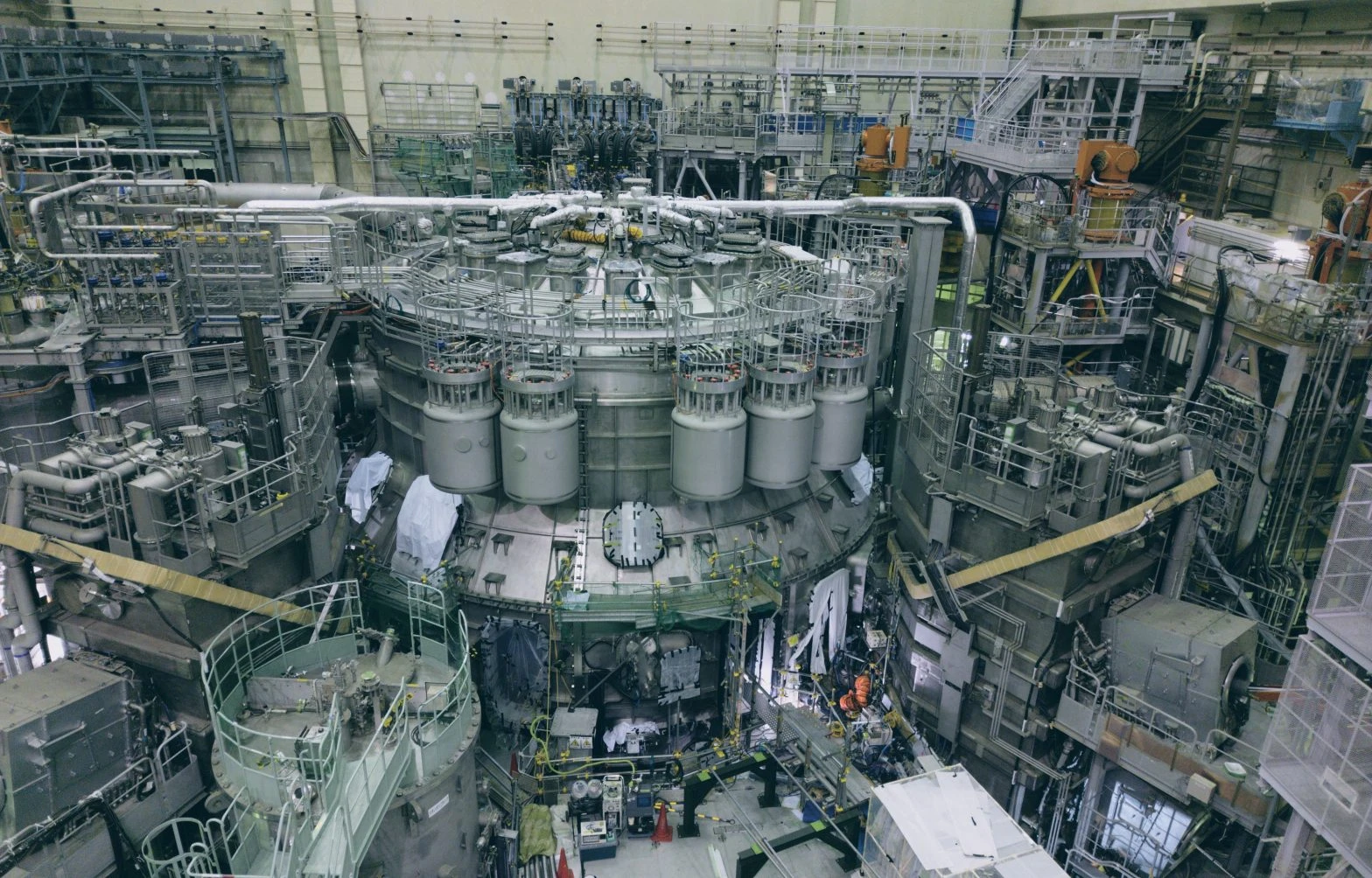
Ten seconds of electricity generation. Twenty-four hours of continuous operation. One reaction every second for several days. The fusion power targets that Japanese organizations and companies have set for the 2030s span this wide a range. All are figures they have yet to demonstrate.
A fusion reaction releases energy. That energy must be converted into electricity, the device’s own consumption subtracted, and the remainder sent out. Fuel must be replenished, worn components replaced, and operation sustained over time. The closer a project gets to a power plant, the more manufacturing and engineering work emerges around the plasma. Both demonstrating the necessary fusion performance and making a power-generation system work, including heat, fuel and maintenance, are essential.
Q-DEMO, FAST, Helix KANATA, EX-Fusion and LINEA. In these five plans, the question of how to produce a reaction meets the question of how to build and operate a plant. Where are research institutions, universities, equipment manufacturers and startups choosing to begin? We trace their approaches through primary sources available as of November 9, 2026. Six comparison tables in the second half bring together their approaches, output, operating duration and scale.
Between fusion power and usable electricity
Three quantities are essential to understanding a power plant. “Fusion power” is the rate of energy released by the fusion reaction. “Gross electrical output” is the electricity extracted from the generating equipment. Subtract the plant’s internal consumption, and what remains is “net electrical output.”
Having 200 MW of fusion power does not mean that 200 MW of electricity can be sent out. Even after net power becomes positive during operation, there are further challenges: the energy balance including startup and shutdown, and supply across an entire year. Connecting a research device to an electricity business depends not just on output, but on which operating conditions can be sustained, and for how many seconds or hours.
The Green Investment Promotion Organization (GIO) provides a picture of the four private-sector routes in published material for its subsidy program to promote fusion power demonstrations. Four proposals are listed as “conditionally selected”: Starlight Engine and Kyoto Fusioneering; Helical Fusion; EX-Fusion and Hamamatsu Photonics; and LINEA Innovations. In the published material, formal selection and grant decisions are to follow once the review committee confirms that the conditions have been addressed. GIO review status and project summaries
Q-DEMO: turning research experience into a reactor that can be built
Q-DEMO draws on Japan’s accumulated research with large devices and its DEMO design work. With QST playing a central role, the project is studying an ITER-sized demonstration reactor using ITER’s technology base. It follows a revision of the earlier JA DEMO concept aimed at earlier realization, rather than a plan to build JA DEMO and Q-DEMO separately.
The Joint Special Design Team for Fusion DEMO, responsible for the design, was established in June 2015. Based at QST’s Rokkasho research site, it brings research institutions, universities and industry together in a nationwide effort on conceptual design and research and development. According to MEXT’s November 9 reference material, it had 226 participants as of November 2025: 109 from industry, 67 from universities and other institutions, and 50 from QST. That mix reflects the breadth of people needed to translate research into equipment. Official description of the joint special team / MEXT Reference Material 3, PDF page 8
This collaboration also influenced the reactor’s size. QST says that, after examining manufacturability with industry, it concluded that bringing construction forward required a design roughly the size of ITER rather than the previous larger concept. A design pursuing performance must be reconciled with the conditions under which it can actually be manufactured. Such design decisions give substance to the nationwide collaboration. This joint design and research structure is, however, separate from deciding who will build and operate a future plant. QST explanation of Q-DEMO’s conceptual design
The next milestone is to develop the design in greater detail. MEXT’s November 9 material sets out a planned transition to engineering design and full-scale technology development in fiscal 2027, taking into account the results of the fiscal 2026 C&R (check and review). The transition depends on the review results. MEXT Reference Material 3, PDF page 17
Power generation, too, is to advance through staged upgrades to a single device. The conceptual design overview targets electricity generation at roughly net-zero power in short pulses of several minutes in Phase 1; operation of at least 30 minutes and fuel breeding in Phase 2; and steady-state operation with approximately 100 MW of net electrical output in Phase 3. Phase 1 pairs 532 MW of fusion power with 10.7 MW net electrical output and a 347-second burn. Gross electrical output is 203 MW: subtracting internal consumption changes the picture substantially. These are all conceptual design values from Table 1, not demonstrated generation. QST conceptual design overview, Table 1
Turning substantial fusion power into usable electricity requires equipment to extract heat, systems to breed and recover fuel, and maintenance to replace components. Linking the areas that can use existing technology with those that need redevelopment for power generation underpins Q-DEMO’s staged approach. Our Q-DEMO introduction explains the basic configuration.
FAST: connecting the engineering for ten seconds of power
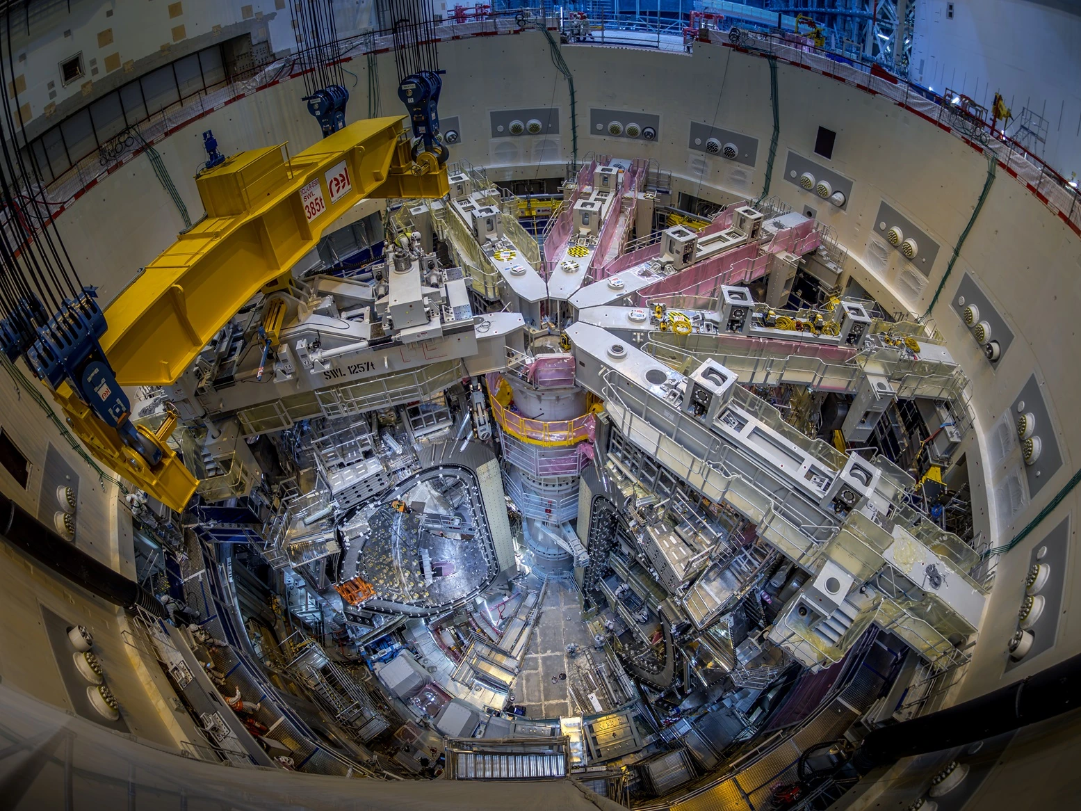
FAST stands for Fusion by Advanced Superconducting Tokamak. It is a high-temperature superconducting tokamak project led by Starlight Engine, with Kyoto Fusioneering also participating in the consortium. It combines compactness enabled by high-temperature superconductivity with integration of the reactor engineering needed to generate electricity.
The plan sets out two operating conditions. The power-generation demonstration targets 200 MW of fusion power and 2 MW of net electrical output for 10 seconds. Basic operation targets 50 MW of fusion power for 1,000 seconds, with no numerical net output specified. The conditions for testing power generation at higher output are separate from those for running longer. Treating 10 seconds and 1,000 seconds as a single performance specification obscures the development goals. Official FAST description / GIO project summary
Even for a short period, extracting net electricity requires the whole device to work together. The blanket receives heat, the heat-circulation system carries it away, and equipment must be integrated with maintenance in mind. The official July 2026 announcement describes engineering design and construction preparations, while the domestic site is at the solicitation and selection stage. The next question is how far a compact reactor core can take shape as a plant that can be built and operated. Starlight Engine progress update / Call for candidate sites
Helix KANATA: what it takes to keep generating for 24 hours
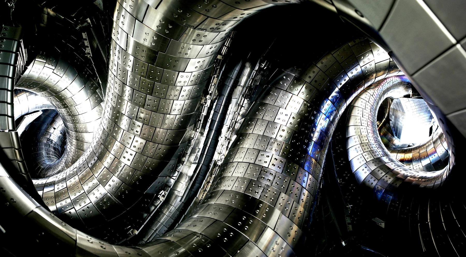
Helical Fusion’s first planned power-generating unit, Helix KANATA, confines plasma with magnetic fields produced by double-helical coils. The GIO summary sets 2030s targets of approximately 200 MW of fusion power, approximately 10 MW of net electrical output and 24 hours of continuous operation. Beyond that lies a “pre-commercial power-generation demonstration” at 50 MW net for 365 days. Extending operating time is central to this plan. GIO project summary
The preceding step is Helix HARUKA, the final demonstration device. It is intended to demonstrate the integration of key technologies and feed the results into KANATA’s design and construction. Phase 1, in manufacturing and construction, is a device intended for magnet demonstration, with its announced site on the NIFS grounds in Toki City. The materials reviewed here do not establish KANATA’s construction site; starting HARUKA construction cannot be counted as starting construction of a power reactor. Helical Fusion siting announcement
A 24-hour target requires heat-handling equipment and fuel systems to keep working throughout that period. Moving on to 365 days means building component lifetimes and replacement methods into the operating plan. Can the knowledge from LHD that the company cites as its foundation be carried through into high-temperature superconducting coils, a liquid-metal-wall blanket, maintenance and plant integration? The design philosophy of long-duration operation will be tested as power-generating equipment.
EX-Fusion: the next fuel target for the next laser shot
The laser approach repeats irradiation of small fuel targets. The proposal led by EX-Fusion, with Hamamatsu Photonics as a consortium member, aims for D-T fusion using direct drive and fast ignition. Lasers compress the fuel, and a separate laser heats it rapidly.
The 2030s targets are 19 MW of fusion power and 1.26 MW of net electrical output. The operating goal is 1 Hz: one reaction every second, repeated for several days. Fiscal 2026–2028 work focuses on the development of core engineering elements and system integration needed to make that possible. GIO project summary
As soon as one irradiation is over, the next fuel target is needed. Targets of consistent quality must be mass-produced and fed in, tracked as they move, and irradiated at the intended moment. The closer the project gets to a power plant, the more weight falls on repeating this sequence without disruption, alongside laser performance itself. Precision manufacturing, control, optics and mass production meet here. The primary sources reviewed do not establish a specific name or construction site for the power-demonstration reactor.
LINEA: seeking a route to electricity with a different fuel
LINEA Innovations proposes a beam-assisted FRC/mirror hybrid approach. FRC, or field-reversed configuration, is a magnetic confinement configuration; the approach uses high-energy particle beams. Its ultimate fuel goal is hydrogen and boron-11, or p-¹¹B. Alongside the four D-T routes, it is exploring a path that differs from the fuel onward.
The GIO summary’s 2030s targets are several MW of fusion power, operation for approximately 100 seconds, and verification of “significant electrical output at the generating end” through direct energy conversion equipment. No numerical target for net electrical output is given. The goal is to combine the reaction region with energy recovery and verify the resulting output. LINEA technology description / GIO project summary
Fiscal 2026–2028 is a stage for developing core equipment and measurement and evaluation infrastructure, leading to a subsequent integrated device. Create the reaction region, inject the beams, recover the energy. The whole plant’s balance emerges only after accounting for the power consumed and energy lost at every step. Reaching the lower costs and lighter maintenance burden the company seeks requires testing that path in actual equipment.
Comparing five routes by approach and numbers
The figures below are published targets or conceptual design values for power-generation demonstrations in the 2030s, not performance already achieved. In the power-output and operating-duration tables, FAST appears in two rows because its operating conditions differ according to the purpose of the run.
Fusion approach and fuel
Comparison table (scroll horizontally)
| Project | Approach and key features | Planned fuel |
|---|---|---|
| Q-DEMO | Magnetic confinement: tokamak, using low-temperature superconducting coils (Nb3Sn/NbTi) | D-T (deuterium and tritium) |
| FAST | Magnetic confinement: high-temperature superconducting tokamak | D-T |
| Helix KANATA | Magnetic confinement: helical configuration, using double-helical high-temperature superconducting coils | D-T |
| EX-Fusion | Laser inertial confinement: compression by direct drive, followed by fast ignition | D-T |
| LINEA | Magnetic confinement: beam-assisted FRC/mirror hybrid, with a non-thermal reaction region using particle beams | Ultimate goal: p-¹¹B (hydrogen and boron-11), with staged development using multiple fuels |
Tokamaks and helical devices both confine plasma with magnetic fields, but differ in coil arrangement and how they use plasma current. The laser approach repeats irradiation of small fuel targets, while LINEA combines high-energy particles with plasma. Even under the same label of “fusion power,” the combination of equipment to be built changes substantially.
Power output
Comparison table (scroll horizontally)
| Project / operating condition | Fusion power, MW | Gross electrical output, MW | Net electrical output, MW |
|---|---|---|---|
| Q-DEMO Phase 1 | 532 | 203 | 10.7 |
| FAST power-generation demonstration | 200 | Unknown | 2 |
| FAST basic operation | 50 | Unknown | Unknown |
| Helix KANATA | Approx. 200 | Unknown | Approx. 10 |
| EX-Fusion | 19 | Unknown | 1.26 |
| LINEA | Several MW | Aim: verify significant output | Unknown |
“Unknown” means that no numerical value is provided in the public materials compared here. It does not mean zero. LINEA’s gross electrical output is described as a goal of verifying electricity extraction through direct energy conversion, rather than as a numerical target.
Operating duration and target timing
Comparison table (scroll horizontally)
| Project / operating condition | Operating duration | Target timing |
|---|---|---|
| Q-DEMO Phase 1 | 347-second burn (approx. 5.8 minutes) | 2030s |
| FAST power-generation demonstration | 10 seconds | 2030s |
| FAST basic operation | 1,000 seconds (approx. 16.7 minutes) | Within the 2030s development plan |
| Helix KANATA | 24 hours | 2030s |
| EX-Fusion | Several days, repeating at 1 Hz | 2030s |
| LINEA | Approx. 100 seconds | 2030s |
The source documents use different terms: “burn duration” for Q-DEMO and “continuous operating duration” in the other proposals. None of these figures represents annual availability. EX-Fusion’s several days refers to operation that repeats a reaction once per second, not the time for which a single plasma is sustained. The target periods are not guarantees of completion or commercial operation.
Compare reactor dimensions separately from site area
“Major radius” is the distance from the torus’s central axis to the center of the plasma or coil. “Minor radius” refers to the radius of the plasma cross-section. Neither is the diameter of the complete reactor or the width of its building.
Comparison table (scroll horizontally)
| Project | Published plasma or coil dimensions | Overall device and site scale |
|---|---|---|
| Q-DEMO | Phase 1 plasma major radius: 6.2 m; minor radius: 2.0 m | Overall device dimensions unknown. A site of up to approximately 100 ha is assumed in the site requirements |
| FAST | In both basic and power-demonstration modes, plasma major radius: 4.0 m; minor radius: 1.35 m | Overall device dimensions for the current design unknown. The call for candidate sites specifies, in principle, at least 60 ha |
| Helix KANATA | The official program description gives a helical-coil major radius of approximately 10 m or more. This is a different measure from plasma major radius | Overall device, building and site dimensions unknown |
| EX-Fusion | Dimensions of the reactor core and irradiation system for the power-demonstration device unknown | Overall device, building and site dimensions for the power demonstration unknown |
| LINEA | Reactor-core dimensions for the power-demonstration device unknown | Overall device, building and site dimensions for the power demonstration unknown |
“Unknown” means that a published value corresponding to the project stage being compared could not be identified in the primary sources reviewed. Reactor-core dimensions, overall device dimensions and site area are different measures and cannot be directly ranked by size.
Q-DEMO’s maximum of approximately 100 ha is a design assumption, while FAST’s minimum of 60 ha in principle is a condition in the call for candidate sites. Neither is the area of land already acquired. KANATA’s approximately 10 m or more describes the concept on the official page that targets operation for at least one year. It could not be confirmed whether this is the same design version as the 24-hour, approximately 10 MW net power-demonstration conditions above.
View layouts and structures in official materials
Comparison table (scroll horizontally)
| Project | Official source | What the illustration shows |
|---|---|---|
| Q-DEMO | Conceptual design overview, PDF page 13 | An example site layout and a cross-section of the tokamak complex building. This is not a rendering of a confirmed construction site |
| FAST | Official project introduction | Device illustrations and specifications. These should be distinguished from a finalized site-wide layout or building dimensions |
| Helix KANATA | Helix Program | A concept illustration of KANATA. HARUKA illustrations are also shown separately; they are not the same device |
| EX-Fusion | Commercial-reactor concept illustration in an official announcement | A concept for a future commercial laser fusion reactor, not the appearance or scale of the power-demonstration device discussed here |
| LINEA | Official technology description | A schematic of the approach combining FRC and mirror configurations, not a dimensioned drawing of the power-demonstration device |
LINEA’s 2025 submission to the government also describes a commercial-reactor concept with “a total length of 30 m and output in the 100 MW class.” This is a different stage from the several-MW power-demonstration device discussed here, so 30 m is not used as the demonstration device’s dimension in the table above.
Current development stage
Comparison table (scroll horizontally)
| Project | Current stage | What is to be verified next |
|---|---|---|
| Q-DEMO | Conceptual design completed in 2026 | Staged development from initial power generation to fuel breeding and steady-state operation |
| FAST | Engineering design and construction preparations | Integration of high-temperature superconducting coils, heat circulation, maintenance and other systems |
| Helix KANATA | HARUKA Phase 1 in manufacturing and construction; KANATA at the design stage | Integration of key technologies, long-duration operation and maintenance |
| EX-Fusion | Development and integration of core engineering elements | Fuel supply, target tracking and irradiation, and high-repetition-rate lasers |
| LINEA | Development of core equipment and measurement and evaluation infrastructure | Reaction region, beam injection and direct energy conversion |
The numerical sources are Table 1 of QST’s conceptual design overview and GIO’s summaries of the four projects. The targets of 10 seconds, 24 hours and 1 Hz show how each project defines a different challenge. Assessing a power demonstration involves more than comparing the size of the numbers.
What can the next few years demonstrate?
All five plans face a shared difficulty: demonstrating one performance measure still leaves technologies that must be brought together for a power plant. Reference material for MEXT’s task force meeting on November 9, 2026, presents the April 8 decision of the task force on social implementation, which assigns two roles to power demonstrations in the 2030s. One is to demonstrate the technical feasibility of a system with market potential. The other is to systematically obtain basic knowledge across the technologies needed for a commercial power plant.
This does not set up a contest based solely on MW or operating duration. It asks whether the targets and development steps toward commercialization have scientific and engineering grounds. The subsequent “pre-commercial power-generation demonstration” is a stage for technically demonstrating a system capable of functioning as a business, on the premise of economic viability. Between extracting electricity once and building a business that sells it, there are still steps to verify. Approach to social implementation, pages 7–8
The support policy calls for developing multiple power-generation systems in parallel, then assessing and selecting systems for concentrated support toward an early demonstration after several years. Research and development support for other promising approaches will also continue. The framework preserves options while using research and development outcomes to inform the next decisions. The coming years of turning today’s figures into test and operating data will provide evidence for those decisions. Same document, pages 5–6
Building a power plant takes work beyond the reactor
Industry’s manufacturability studies for Q-DEMO, FAST’s heat circulation, and the repeated fuel supply and irradiation sought by EX-Fusion all connect research with manufacturing on the way to a power plant. Having different approaches also means companies have more than one point of entry.
But assembling excellent components does not automatically produce a power plant. Equipment tested separately must be connected, each part withstanding its required temperatures and loads while the system as a whole operates for the necessary duration. After a maintenance shutdown, it must run again. The work of closing the gap between component performance and plant performance cannot fit into a single column of an output table.
Five plans do not mean that five reactors have been confirmed for construction in Japan. Nor can Q-DEMO’s design base or HARUKA’s construction site be substituted for future power-plant locations. Can these projects make financing, siting, safety and procurement concrete, build the equipment and obtain operating data? That is the capability now being tested.
Ten seconds of generation, 24 hours of operation, and reactions repeated every second all require people who can turn drawings into equipment, connect that equipment and keep it working. From the joint design effort in Rokkasho to the development work of startups and manufacturers, those people are already part of the plans. The task is to turn numbers on drawings into operating power plants. These five plans seek to test Japan’s accumulated research and manufacturing strength as a practical ability to produce electricity.
- GIO: Review status and conditional selection
- GIO: EX-Fusion and Hamamatsu Photonics project summary
- GIO: Helical Fusion project summary
- GIO: LINEA Innovations project summary
- GIO: Starlight Engine and Kyoto Fusioneering project summary
- QST: Q-DEMO conceptual design overview, Table 1
- QST: DEMO research and development
- Starlight Engine: FAST project and device specifications
- Starlight Engine: July 2026 progress update
- Starlight Engine: Call for FAST candidate sites
- Helical Fusion: HARUKA Phase 1 construction site announcement
- LINEA Innovations: Technology overview
- Helical Fusion: KANATA concept figures and illustrations in the Helix Program
- EX-Fusion: Official announcement including a commercial-reactor concept illustration
- LINEA: Commercial concept in the October 15, 2025 submission to the government
- MEXT: First Technology Development Strategy Task Force meeting, November 9, 2026, Reference Material 3
- Task Force on Social Implementation: Approach to the Social Implementation of Fusion Energy
- Joint Special Design Team for Fusion DEMO: Official overview
Information checked as of:2026-11-09
Checked against primary sources. Figures are published targets or conceptual design values, not achieved electricity generation. The four private-sector projects are listed as conditionally selected in the cited material. This does not mean that construction of five reactors in Japan has been approved.