Why upright coils make a field around the ring: TF, PF and the central solenoid
Tokamak magnets differ in both arrangement and function. ITER's TF coils, PF coils and central solenoid show how coil orientation, field direction and plasma current fit together.
Read the Japanese original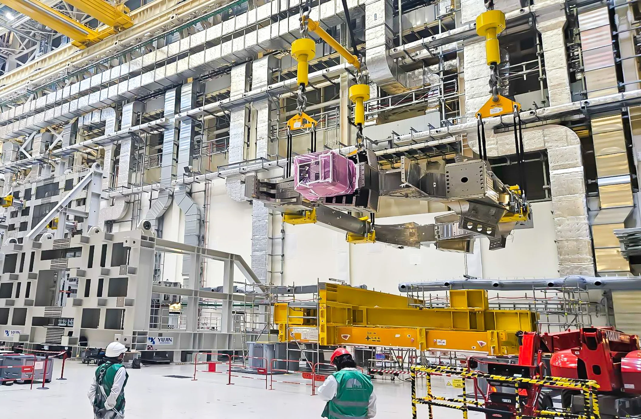
Tokamak photographs show enormous upright D-shaped components, horizontal rings and a cylindrical magnet assembled on the central axis. All are coils that use electric current to produce magnetic fields, but they do not do the same job.
The key is to distinguish the orientation of a coil from the direction of the magnetic field it produces. Using ITER as an example, we look at TF coils, PF coils and the central solenoid. See FI's tokamak overview for the broader approach and FI's tokamak 3D guide for the spatial arrangement.
TF: upright coils produce a field around the ring
TF stands for toroidal field. The toroidal direction runs around the large ring of a doughnut-shaped torus. ITER has 18 D-shaped coils arranged around its vacuum vessel to produce this field.
It is misleading to assume that an upright coil must create an upward field. Current in a coil and the magnetic field it creates do not point in the same direction. Upright D-shaped loops arranged around the machine produce a field in the toroidal direction. The name TF describes the principal field direction, rather than the coil's visual orientation.
The TF field alone does not complete tokamak confinement. It combines with the field produced by current flowing in the plasma, giving the field lines a helical form. IPP's explanation describes how this combination forms magnetic surfaces needed to confine the plasma.
PF: horizontal rings control plasma shape and position
PF stands for poloidal field. The poloidal direction goes around the cross-section of the doughnut, rather than around its large ring.
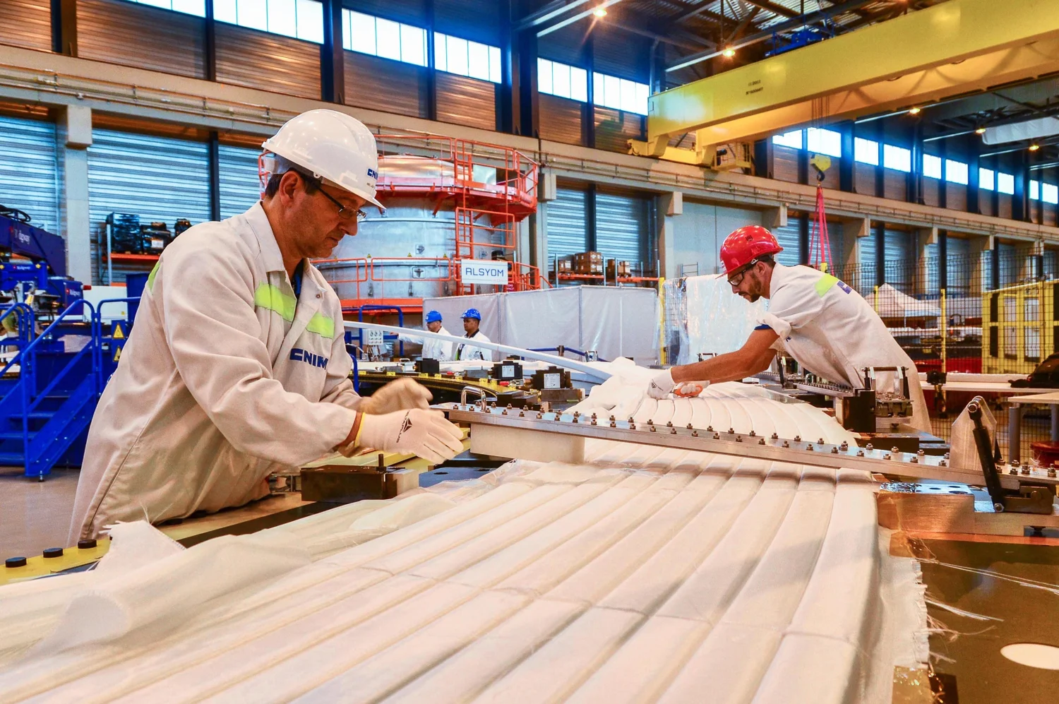
ITER has six ring-shaped PF coils outside its TF coil structure. They shape the plasma and help keep it stable and away from the wall. The photograph shows PF5 winding manufacture published in 2018, not a completed operating machine or a present-day plasma.
Another simplification to avoid is that all poloidal field comes from PF coils. Plasma current also produces poloidal field. Distinguishing a component's name from the complete field inside the machine makes structural diagrams easier to read.
Sources: ITER's magnet system, PF5 manufacturing record
The central solenoid: changing flux induces plasma current
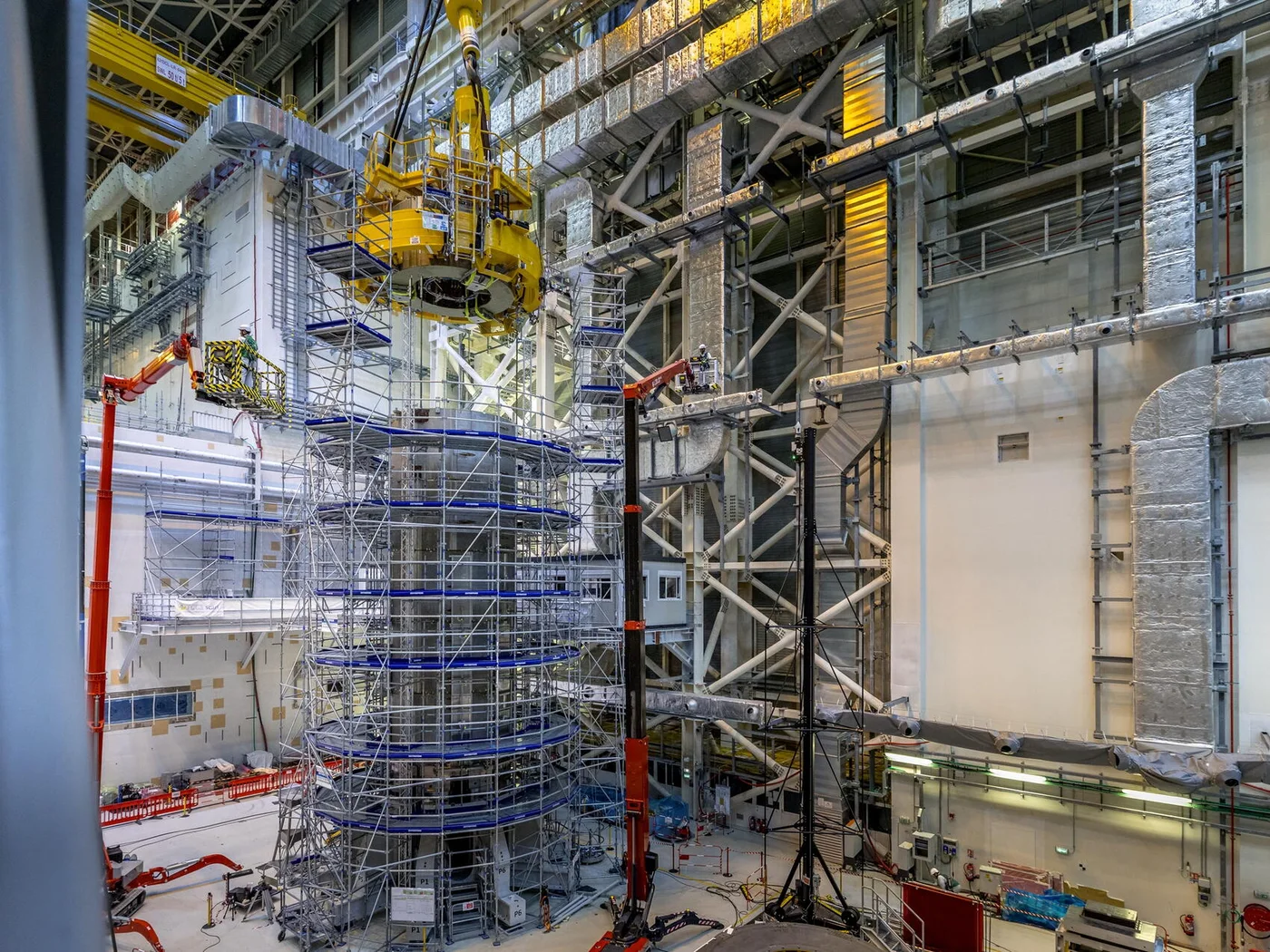
The central solenoid, or CS, sits on the central axis, in the hole of the torus. ITER's CS consists of six independently operated coil modules stacked together. Like TF and PF coils it is a magnet, but a key function is to induce current in the plasma.
The principle resembles a transformer. Changing current in the central coil changes magnetic flux, creating an electric field that drives current around the plasma ring. The plasma is not supplied with this current simply by inserting an external electrical wire.
Holding the central solenoid in an unchanging state therefore cannot sustain inductive current drive indefinitely. Other current-drive methods, including radio-frequency techniques, are being studied for future steady-state operation. This does not mean the CS has no role. It means that longer operation also requires attention to how the plasma current is produced.
The photograph records the stacking of the sixth CS module on 23 June 2026. It documents assembly, not plasma operation or electricity generation.
Sources: ITER's assembly record, IPP's tokamak explanation
Separate the photographed shape from the operating function
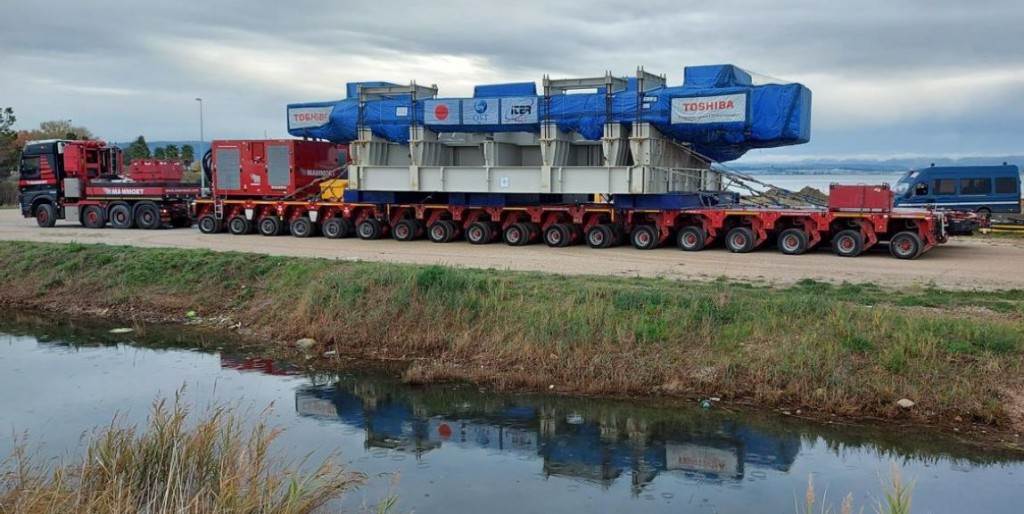
A coil may lie horizontally during transport and be covered in protective material. Its transport position does not directly reveal the direction of its operating magnetic field. When reading a photograph, check the component name, its installed arrangement and its function when energized.
These three categories are not the entire machine. ITER also has coils that correct field errors and in-vessel coils for additional plasma control. Power supplies, cooling and support structures are also part of the magnet system.
Start with the main roles: TF produces the field around the ring, PF controls shape and position, and CS induces current. Asking which component was tested, and for what purpose, turns a photograph of an enormous magnet into a way to understand technical progress.
TF, PF and the central solenoid at a glance
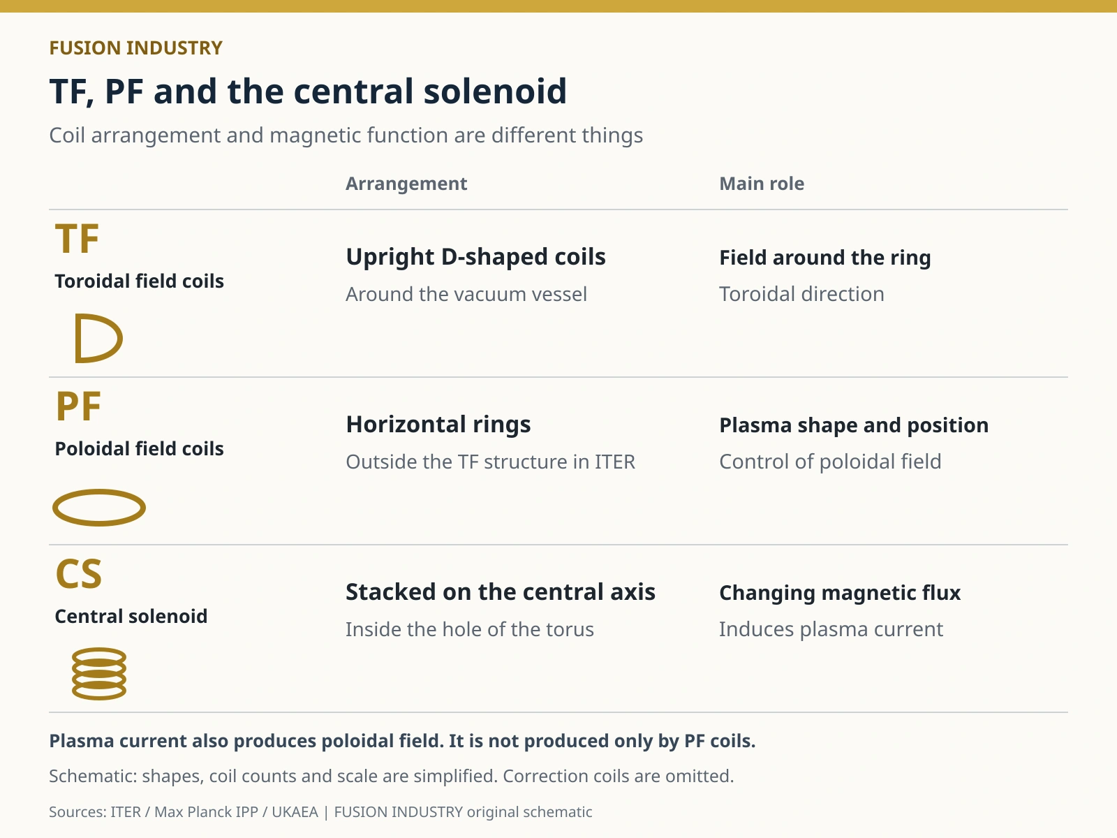
- ITER | Magnets: configuration and principal functions
- Max Planck IPP | Tokamak: combined fields and induced current
- UKAEA | The tokamak: component functions
- ITER | Turning tables and hot resin: PF5 manufacture, 23 July 2018
- ITER | Tokamak Assembly: photographs of TF07 and the central solenoid
- ITER | Component Transport: TF10 transport, 15 November 2021
Information checked as of:2026-11-04
An explanation using ITER as an example. The photographs document manufacturing, transport and assembly at their stated dates, not plasma operation or electricity generation.