Measuring electron temperature with a laser
Sending, collecting and filtering light to measure electron temperature: JT-60SA’s ten-tonne support and COMPASS specifications reveal the engineering behind a plasma diagnostic.
Read the Japanese originalAnnouncement date:2026-11-16
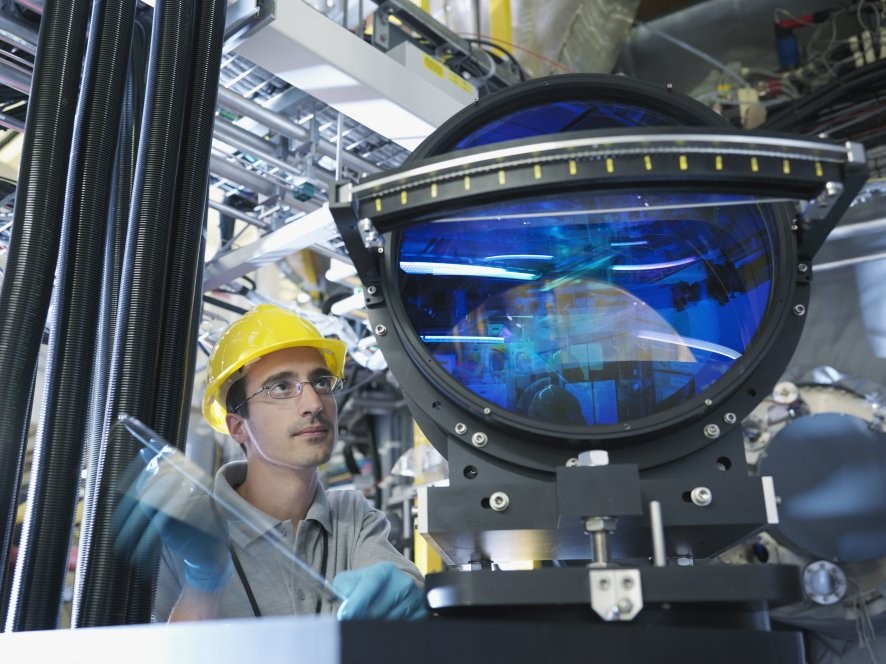
Measuring plasma temperature can require a ten-tonne support structure. In 2025, JT-60SA installed a frame for a diagnostic that measures electron temperature and density. It does not insert a thermometer into the plasma: it sends in a laser and collects light scattered by electrons. Why does measuring a small optical change require so much hardware?
Light reveals electron motion
Thomson scattering examines laser light redirected by electrons. Their motion shifts its wavelength through the Doppler effect. A distribution of electron velocities produces a broadened spectrum, from which electron temperature is inferred. Calibrated signal intensity gives electron density. COMPASS diagnostic
This is electron temperature, not ion temperature or wall temperature. A reported plasma temperature needs both a measured population and a location.
Finer detail means less light
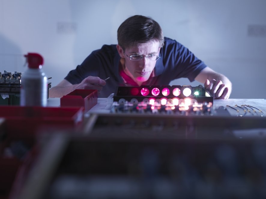
COMPASS lists two lasers, each delivering 1.5-joule pulses lasting seven nanoseconds. Optical fibres carry the scattered light to spectral analysers. Filters, detectors and digitizers complete the measurement chain.
The ITER International School lecture explains a design trade-off: narrowing the collection region along the laser improves spatial resolution but reduces the signal. Widening it across the beam tolerates more misalignment but also collects more background light. A larger lens alone cannot settle the problem.
ITER reported that MAST completed a £2 million Thomson-scattering upgrade in September 2009. The MAST photographs here come from that contemporary account. Rather than producing a single temperature, the diagnostic probes temperature and density profiles, requiring both the delivery and collection of light. MAST upgrade
Ten tonnes to support the optics
F4E reported on September 30, 2025 that the JT-60SA edge Thomson scattering support structure was positioned with millimetric precision. The work included a ramp and trolley for inserting optical components. The ten tonnes refers to the support structure, not to the laser itself.
FI’s reading is that detector sensitivity is only part of the engineering value. Optical alignment depends on structures that can be designed, manufactured and installed together.
The optical path needs testing too
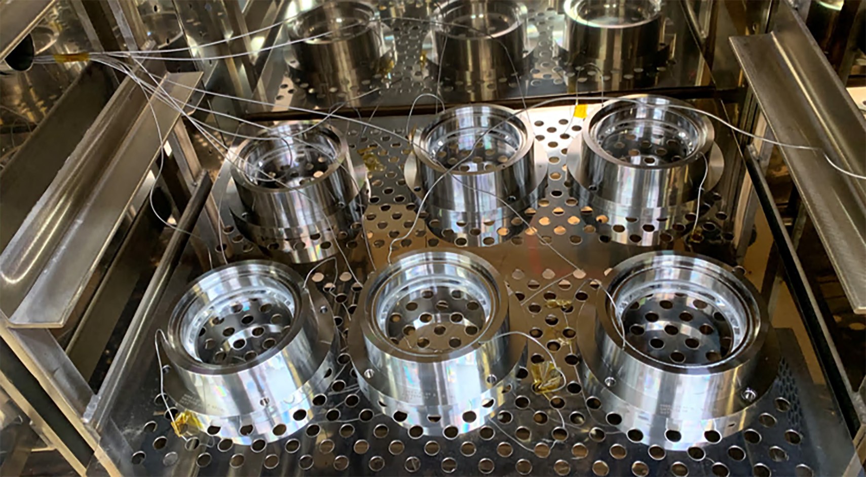
In 2023, ITER described diagnostic-window prototypes tested through 500 thermal cycles between room temperature and 240°C. A window must transmit light while preserving the vacuum. Window tests
Keeping deposits off the mirrors
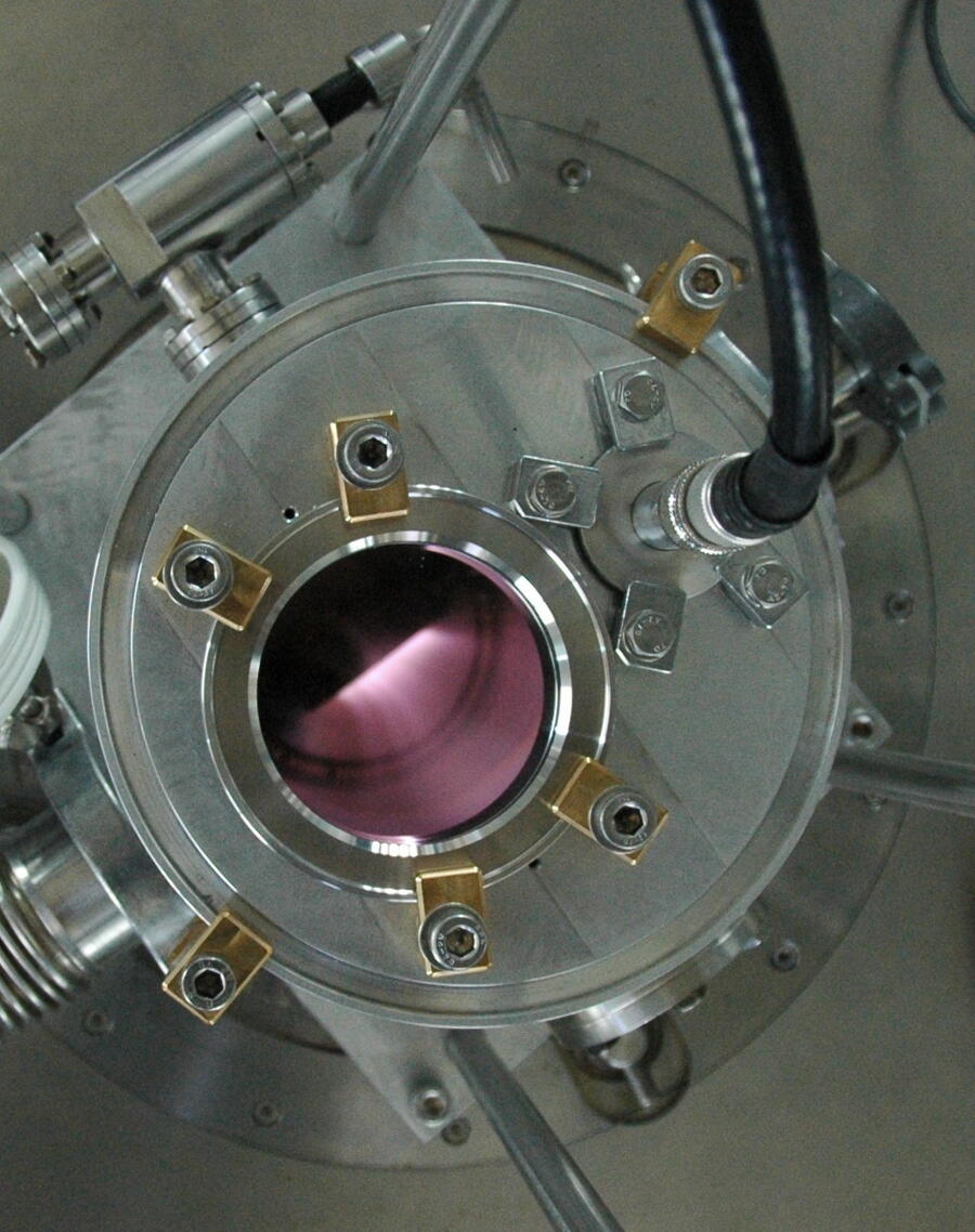
Deposits on mirrors also affect the light reaching a detector. In 2015, ITER reported research on plasma cleaning of diagnostic mirrors. These are examples of optical-diagnostic development, not components identified as the same JT-60SA system. Mirror-cleaning tests
What stands behind a temperature
ITER’s diagnostic strategy calls for important quantities to be measured redundantly, preferably through different methods. Thomson scattering is one contributor, not a complete test of power-plant performance. When reading a temperature milestone, look also at which particles were measured, where, and with what temporal and spatial detail.
Optical systems map temperature and density, while other diagnostics address neutrons and impurities. Behind the reported number is hardware designed to retain useful light and reject unwanted light.
- Thomson scattering — ITER International School 2024
- COMPASS Thomson-scattering diagnostics — Czech Academy of Sciences
- F4E: JT-60SA diagnostics upgrade and support structure (30 September 2025)
- ITER diagnostic systems
- ITER diagnostic-window vacuum and thermal-cycle tests
- ITER diagnostic-mirror cleaning tests
- ITER: MAST Thomson-scattering upgrade (4 December 2009)
Information checked as of:2026-11-16
Measurement principles, published specifications and installation reports checked against primary sources. Plans, completed work and the equipment shown in each photograph are distinguished.