Where will a fusion plant cool itself? Siting through water and heat-rejection requirements
Cooling systems connect site water supply, discharge and operating costs. ITER illustrates the difference between circulating and makeup water, time-varying heat loads and conditions for potential waste-heat users.
Read the Japanese original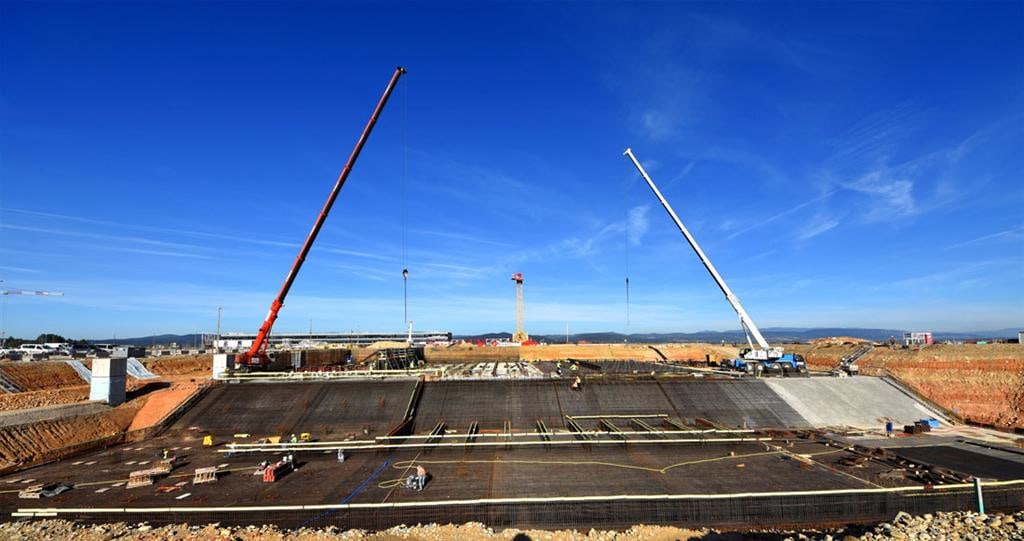
When considering a fusion plant site, water sources and the destination for rejected heat deserve attention alongside land area and grid connection. Cooling systems affect not only construction costs but operating electricity, water treatment and the layout of surrounding equipment. ITER's cooling facilities illustrate how to translate these conditions into a business plan.
ITER's cooling work extends beyond the reactor
ITER's cooling tower and basin area covers approximately 6,000 square meters, with pumps, heat exchangers and ten cooling tower cells. The official page describes it as currently operating to support commissioning of other systems. ITER is an experimental machine that does not generate electricity, so its scale cannot be transferred directly to future commercial reactors. ITER cooling tower area
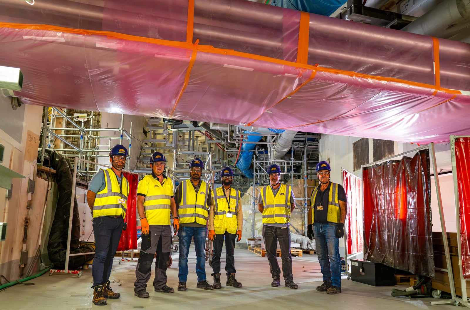
Cooling serves not only the vacuum vessel and in-vessel components but also heating equipment and power supplies. Heat passes through several closed circuits and heat exchangers before reaching an open heat-rejection system. Cooling towers evaporate some water to release heat, and the cooled water is reused. Cooling system configuration
This shows that even after reactor performance is specified, piping, water quality, pumps, diagnostics and controls must be integrated. Cooling design needs information on when heat arrives from each component and in what quantity.
Distinguish circulating flow from external makeup water
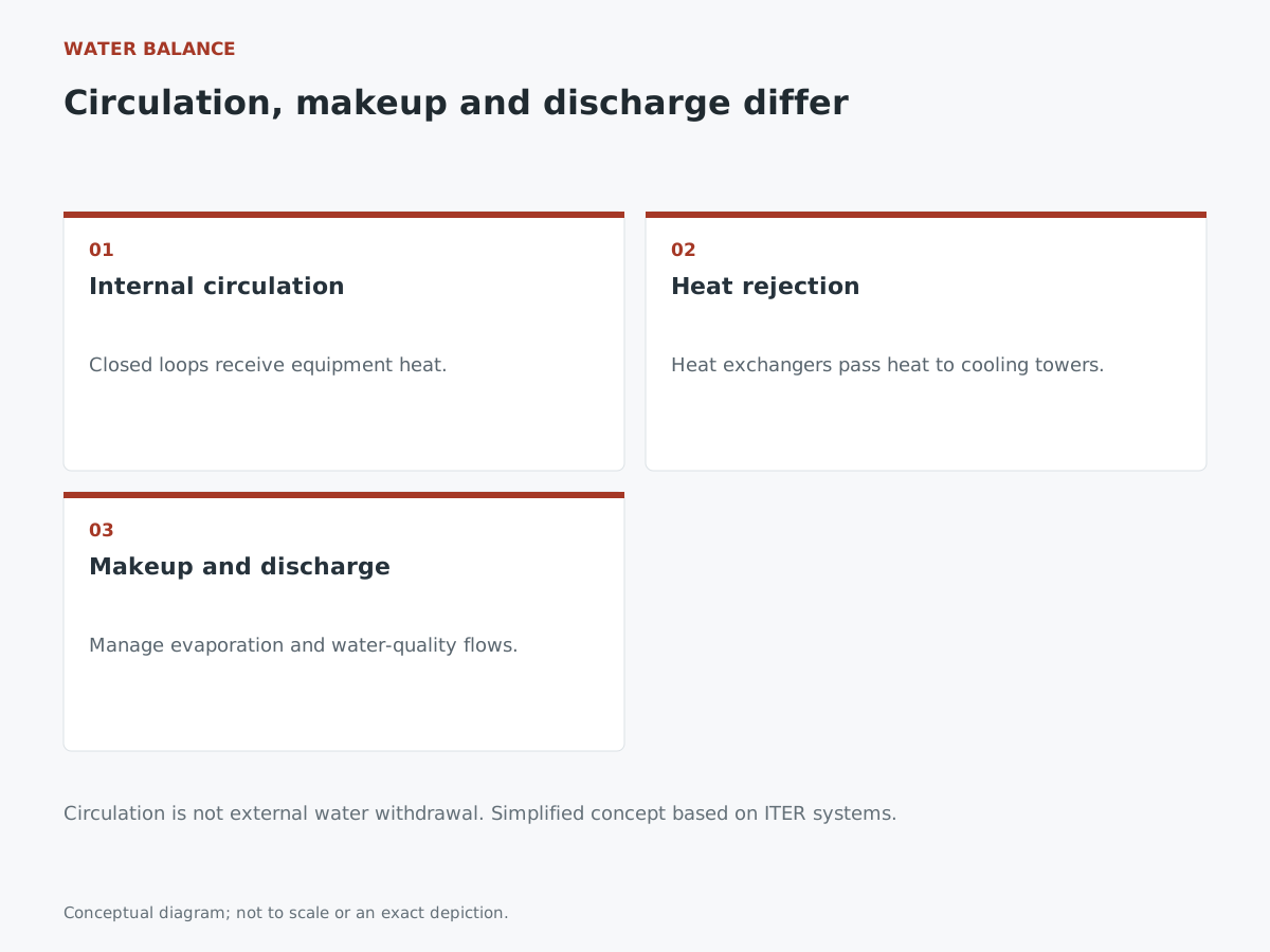
ITER describes a combined flow of approximately 33 cubic meters per second through its cooling loops during plasma operation. This is the sum of internal circulating flows, not the same volume being drawn from outside every second.
Circulation does not eliminate makeup water, however. Evaporation concentrates substances in ITER's water, so some is discharged and replenished from the Canal de Provence. Discharge water is checked for temperature and quality in monitoring basins before compliant water is released into the Durance River. Makeup water and discharge management
The following is editorial analysis. A site comparison should list internal circulation, external makeup and discharge separately rather than using a single “cooling water” figure. Pump capacity, supply costs and treatment capacity depend on different quantities. ITER's discharge conditions should not be treated as standards for Japanese sites; local conditions require individual investigation.
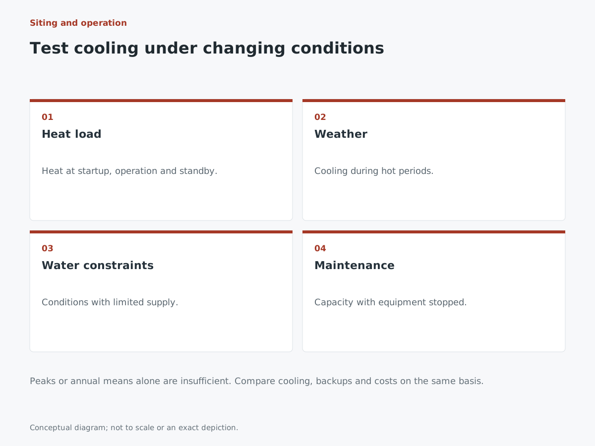
Examine variation over time, not just peak load
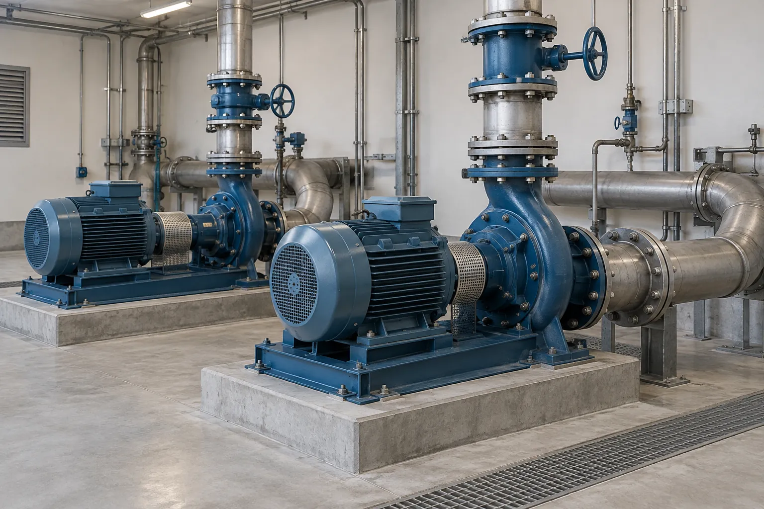
ITER-India describes a heat-rejection design averaging approximately 510 MW to the atmosphere, with warm-water basins storing some heat concentrated during plasma burn periods. The basins buffer the time variation in heat production against cooling tower operation. ITER-India's design explanation
This is an ITER design value, not measured fusion-burn performance or a standard commercial power plant specification. The lesson for companies is to share heat loads as time series covering operation, standby and startup, rather than a single maximum.
Average annual temperature is also insufficient for site assessment. Compare hot-weather cooling conditions, constrained water supplies and maintenance of part of the system with the designers. Evaluating added costs and operating ranges for alternative cooling methods or standby equipment on consistent assumptions may change the ranking of an apparently inexpensive site.
If selling waste heat, start with the user's requirements
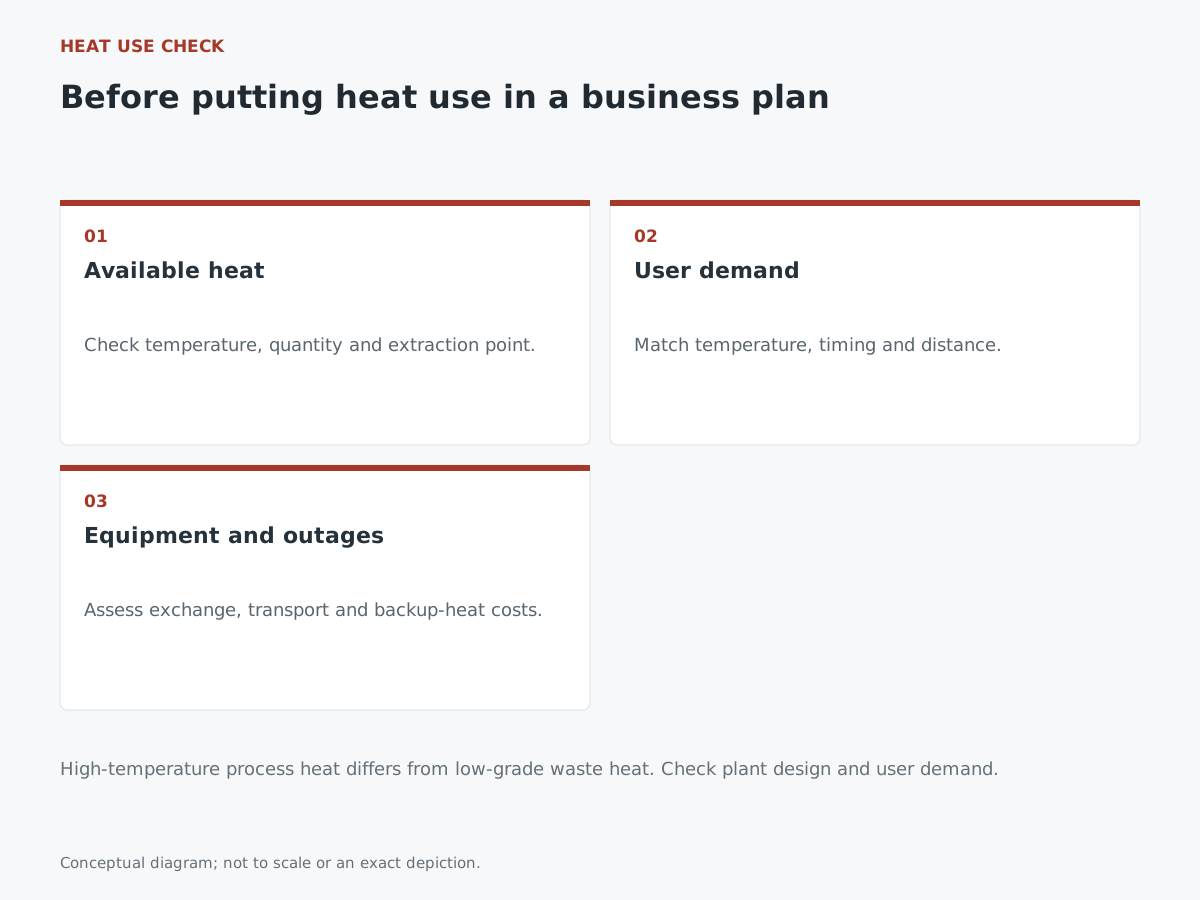
Supplying rejected heat to factories or local demand could broaden business options. The existence of heat alone does not justify booking revenue. Australian government guidance for general industry also recommends assessing variations in temperature, flow and composition, alongside location and timing constraints. Waste-heat recovery considerations
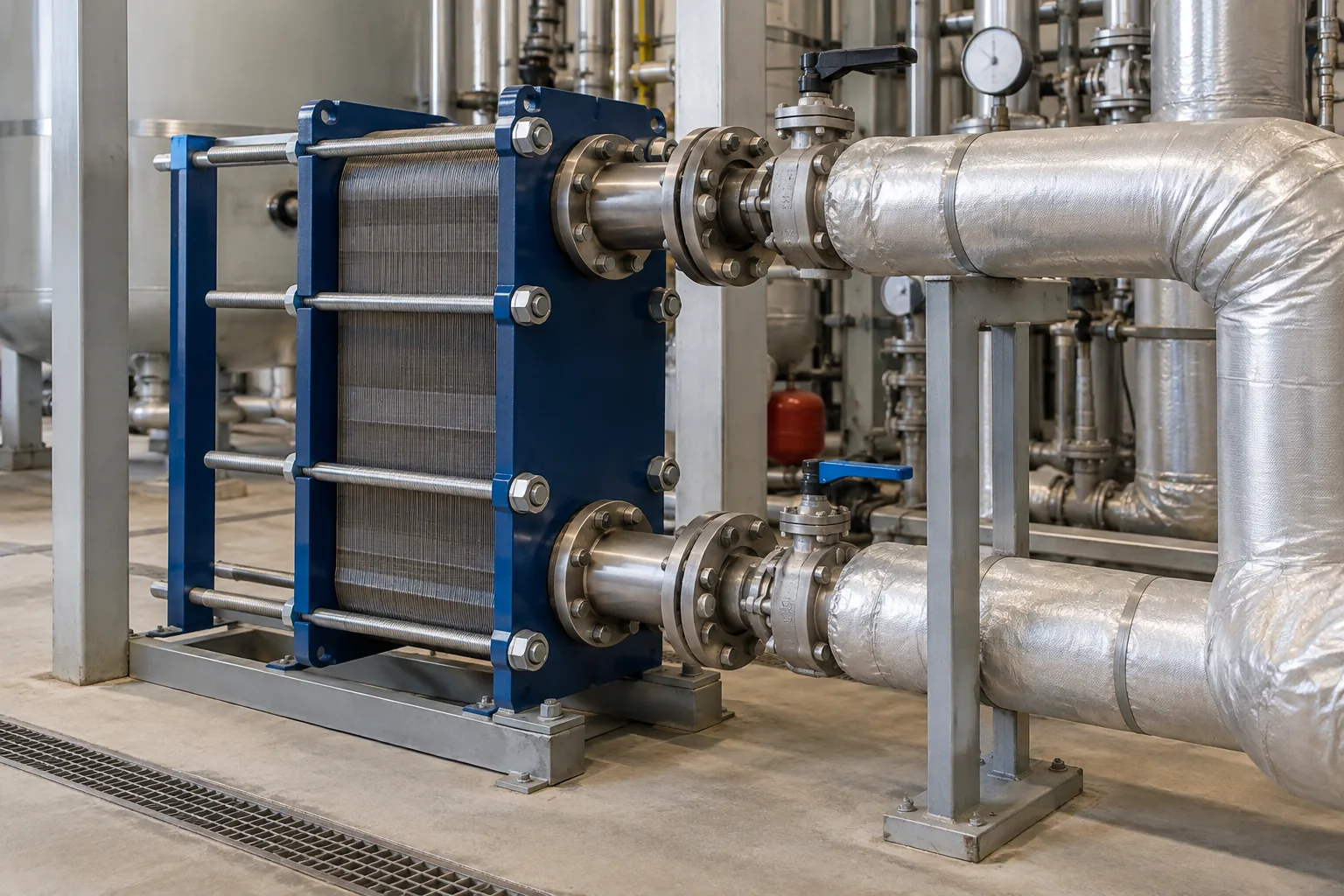
Applying this to future fusion plants is an editorial proposal. First establish the user's required temperature and supply hours, piping distance and heat-exchange costs. Consider which backup source the user would employ during interruptions. Do not group high-temperature process heat with lower-temperature heat remaining after generation and cooling; state where the heat is extracted.
Add a one-page water and heat balance to the business plan
Early investigations should summarize expected makeup water and discharge for each site, time-varying heat loads, cooling-system electricity consumption and heat-user conditions. For unresolved items, identify whom to consult and the cost of further investigation.
Water treatment, pump, heat-exchanger and plant-design companies can help make those uncertainties concrete. Rather than waiting for the reactor to be completed, consider participation at the stage of obtaining heat and water data from developers and comparing combinations of sites and equipment. This is business analysis based on public material, not a guarantee of open procurements or returns.
Official information from related companies and research institutions
Check each organization’s announcements for development progress and technical documentation.
- ITER | Cooling Tower Area (configuration and operation supporting commissioning)
- ITER | Cooling water (circulation, makeup and discharge management)
- ITER-India | Cooling Water System of ~510 MW Heat Rejection capacity (design load and warm-water basins)
- Australian government, energy.gov.au | Waste heat recovery (general industrial applications)
Information checked as of:2026-10-09
ITER configuration and operating status are described as of October 9, 2026. Approximately 510 MW is an ITER-India design value, not a measured result. Site water and heat balances and costs need individual assessment.